Infiniti I35 (A33). Manual - part 483


  Index      Infiniti     Infiniti I35 (A33) - service repair manual 2004 year


Search            


Content   ..  481  482  483  484   ..


Infiniti I35 (A33). Manual - part 483


SEM418G

I

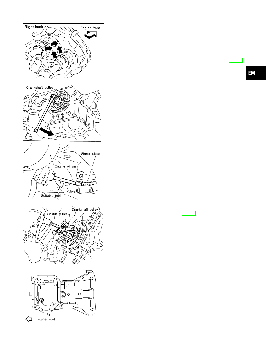
Check that intake and exhaust cam nose on No. 1 cylinder are
located as shown.
If not, turn the crankshaft one revolution (360°) and align as
shown.
When only primary timing chain is removed, rocker cover does
not need to be removed. To confirm that No. 1 cylinder is at its
compression TDC, remove front timing chain case first. Then
check mating marks on camshaft sprockets. Refer to EM-39,
“Installation”.

SEM965F

17. Loosen crankshaft pulley bolt. (At this time remove oil pan rear

cover plate and set a suitable tool to ring gear so that crank-
shaft cannot rotate.)

I

Be careful not to damage the signal plate teeth.

SEM915E

18. Remove crankshaft pulley with a suitable puller.
19. Remove steel oil pan. Refer to EM-14, “Removal”.

SEM921G

20. Loosen bolts in reverse order shown in figure, and remove

installation bolts at the front of aluminum oil pan.

21. Install steel oil pan temporarily.
22. Support steel oil pan bottom with a transmission jack.

I

Perform following operations with engine front-side supported
with jack.

GI

MA

LC

EC

FE

AT

AX

SU

BR

ST

RS

BT

HA

SC

EL

IDX

FRONT TIMING CHAIN CASE

Removal (Cont’d)

EM-23

SEM728G

23. Remove center member assembly.
24. Remove intake valve timing control covers.

I

Loosen bolts in reverse order shown in the figure.

I

In the cover, the shaft is engaged with the center hole of the
intake camshaft sprocket. Remove it straight out until the
engagement comes off.

25. Remove right side engine mounting, mounting bracket and

nuts. Refer to EM-69, “Removal and Installation”.

26. Raise engine front-side with jack. (This secures workspace to

remove front timing chain case.)

SEM730G

27. Loosen front timing chain case bolts in reverse order shown in

the figure.

SEM156F

28. Remove front timing chain case.
a.

Insert the appropriate size tool into the notch at the top of the
front timing chain case as shown (1).

b.

Pry off the case by moving the tool as shown (2).

I

Use seal cutter (special service tool) or an equivalent tool to
cut liquid gasket for removal.

CAUTION:

I

Do not use screwdrivers or something similar.

I

After removal, handle it carefully so it does not tilt, cant,
or warp under a load.

29. Remove water pump cover and timing chain tensioner cover

from front timing chain case.

I

Use seal cutter (special service tool) or an equivalent tool to
cut liquid gasket for removal.

30. Remove front oil seal from front timing chain case.

Refer to EM-48, “FRONT OIL SEAL”.

31. Remove timing chain and related parts. Refer to EM-29, “TIM-

ING CHAIN”.

Installation

NHEM0070

1.

Install timing chain and related parts. Refer to EM-29, “TIMING
CHAIN”.

2.

Remove residual gasket from front timing chain case and liq-
uid-gasket mating surface.

CAUTION:

Be careful not to allow gasket fragments to enter oil pan.

FRONT TIMING CHAIN CASE

Removal (Cont’d)

EM-24

PBIC1101E

3.

Hammer dowel pins (right and left) into front timing chain case
up to a point close to taper in order to shorten protrusion
length.

SEM715A

4.

Install the front oil seal on the front timing chain case. Apply
new engine oil to the oil seal edges.

I

Install it so that each seal lip is oriented as shown in figure.

PBIC0790E

I

Using a suitable drift, press-fit oil seal until it becomes flush
with front timing chain case end face.

I

Make sure the garter spring is in position and seal lip is not
inverted.

SEM744GA

5.

Install the water pump cover and the chain tensioner cover to
front timing chain case cover.

I

Apply RTV Silicone Sealant or equivalent. Refer to GI-53, “REC-
OMMENDED CHEMICAL PRODUCTS AND SEALANTS” and
LC-16, “Installation”.

GI

MA

LC

EC

FE

AT

AX

SU

BR

ST

RS

BT

HA

SC

EL

IDX

FRONT TIMING CHAIN CASE

Installation (Cont’d)

EM-25

PBIC0913E

6.

Install front timing chain case as follows:

a.

Apply liquid gasket to front timing chain case back side as
shown.

b.

Install dowel pin on the rear timing chain case into dowel pin
hole on front timing chain case.

PBIC1099E

7.

Apply liquid gasket to top surface of oil pan (upper) as shown
in figure.

I

Use Genuine RTV Silicone Sealant or equivalent. Refer to
GI-53, “RECOMMENDED CHEMICAL PRODUCTSAND SEAL-
ANTS”.

PBIC1100E

8.

As shown in figure, assemble front timing chain case.

a.

Fit lower end of front timing chain case tightly onto top face of
oil pan (upper). From the fitting point, make entire front timing
chain case contact rear timing chain case completely.

CAUTION:

Be careful that oil pan gasket is in place.

PBIC1115E

b.

While pressing front timing chain case from its front and top as
shown in figure, install bolts and temporarily tighten them.
For bolt length and positions, refer to the step 9.

c.

Hammer dowel pin until the outer end becomes flush with sur-
face.

FRONT TIMING CHAIN CASE

Installation (Cont’d)

EM-26


Content   ..  481  482  483  484   ..