Infiniti I35 (A33). Manual - part 484
SEM730G
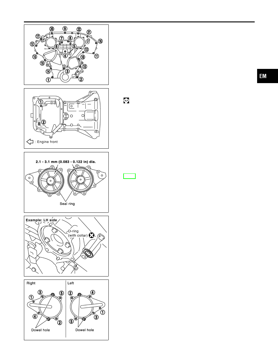
9.
Tighten bolts to the specified torque in order shown in the fig-
ure.
8 mm (0.31 in) dia. bolts: 1, 2
6 mm (0.24 in) dia. bolts: Except the above
I
After tightening, retighten them to specified torque in numeri-
cal order shown in figure.
SEM921G
10. Tighten two mounting bolts in front of oil pan (upper) in numeri-
cal order shown in figure.
: 15.7 - 18.6 N·m (1.6 - 1.9 kg-m, 12 - 13 ft-lb)
KBIA1314E
11. Install RH and LH intake valve timing control covers as follows:
a.
Install seal rings in shaft grooves.
b.
Apply liquid gasket to the intake valve timing control covers.
I
Use Genuine RTV Silicone Sealant or equivalent. Refer to
GI-53, “RECOMMENDED CHEMICAL PRODUCTSAND SEAL-
ANTS”.
SEM948G
c.
Install collared O-ring in front timing chain case oil hole (LH
and RH sides).
SEM728G
d.
Being careful not to move the seal ring from the installation
groove, align the dowel pins on the chain case with the holes
to install the intake valve timing control covers.
e.
Tighten bolts in the numerical order as shown.
GI
MA
LC
EC
FE
AT
AX
SU
BR
ST
RS
BT
HA
SC
EL
IDX
FRONT TIMING CHAIN CASE
Installation (Cont’d)
EM-27