Infiniti I35 (A33). Manual - part 383


  Index      Infiniti     Infiniti I35 (A33) - service repair manual 2004 year


Search            


Content   ..  381  382  383  384   ..


Infiniti I35 (A33). Manual - part 383


SEL179W

SEL613Y

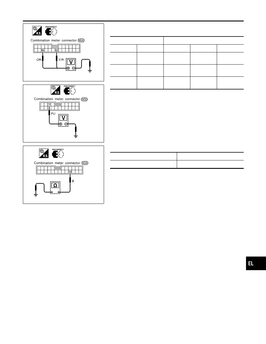
POWER SUPPLY AND GROUND CIRCUIT CHECK

=NHEL0046S07

Power Supply Circuit Check

NHEL0046S0701

Terminals

Ignition switch position

(+)

(−)

OFF

ACC

ON

31

Ground

0V

Battery
voltage

Battery
voltage

62

Ground

Battery
voltage

Battery
voltage

Battery
voltage

66

Ground

0V

0V

Battery
voltage

If NG, check the following.

I

10A fuse [No. 12, located in fuse block (J/B)]

I

10A fuse [No. 30, located in fuse block (J/B)]

I

10A fuse [No. 1, located in fuse block (J/B)]

I

Harness for open or short between fuse and combination
meter

SEL180W

Ground Circuit Check

NHEL0046S0702

Terminals

Continuity

59 - Ground

Yes

GI

MA

EM

LC

EC

FE

AT

AX

SU

BR

ST

RS

BT

HA

SC

IDX

METERS AND GAUGES

Trouble Diagnoses (Cont’d)

EL-133

INSPECTION/VEHICLE SPEED SIGNAL

=NHEL0046S03

With VDC

NHEL0046S0301

1

CHECK VEHICLE SPEED SENSOR OUTPUT

1. Remove vehicle speed sensor from transmission.
2. Check voltage between combination meter harness connector M214 terminal 15 (R) and ECM harness connector F48

terminal 58 (B) while quickly turning speed sensor pinion.

SEL181WA

OK or NG

OK

©

Vehicle speed sensor is OK.

NG

©

GO TO 2.

2

CHECK VEHICLE SPEED SENSOR

Check resistance between vehicle speed sensor terminals 1 and 2.

SEL645W

OK or NG

OK

©

Check harness or connector between speedometer, vehicle speed sensor and ECM.

NG

©

Replace vehicle speed sensor.

METERS AND GAUGES

Trouble Diagnoses (Cont’d)

EL-134

With TCS

NHEL0046S0302

1

CHECK ABS/TCS CONTROL UNIT OUTPUT SIGNAL

With CONSULT-II

1. Lift up drive wheels.
2. Start engine and drive vehicle at more than 20 km/h (12 MPH).
3. Check signal between combination meter harness connector M33 terminal 15 (R) and ground when rotating wheels

with engine at idle. (Use “SIMPLE OSCILLOSCOPE” in “SUB MODE” with CONSULT-II.)

SEL938W

Without CONSULT-II

1. Lift up drive wheels.
2. Start engine and drive vehicle at more than 20 km/h (12 MPH).
3. Check voltage between combination meter harness connector terminal 15 and ground when rotating wheels with

engine at idle.

SEL939W

OK or NG

OK

©

ABS/TCS control unit is OK.

NG

©

Check the following.

I

Harness for open or short between ABS/TCS control unit and combination meter.

I

ABS/TCS control unit. Refer to BR-61, “Wheel Sensor or Rotor”.

GI

MA

EM

LC

EC

FE

AT

AX

SU

BR

ST

RS

BT

HA

SC

IDX

METERS AND GAUGES

Trouble Diagnoses (Cont’d)

EL-135

INSPECTION/ENGINE REVOLUTION SIGNAL

NHEL0046S02

1

CHECK ECM OUTPUT

1. Start engine.
2. Check voltage between combination meter harness connector M33 (with TCS) or M214 (with VDC) terminals 16 (W/G)

and ground at idle and 2,000 rpm.

SEL364WD

OK or NG

OK

©

Engine revolution signal is OK.

NG

©

Harness for open or short between ECM and combination meter

METERS AND GAUGES

Trouble Diagnoses (Cont’d)

EL-136


Content   ..  381  382  383  384   ..