Infiniti I35 (A33). Manual - part 381
Component Parts and Harness Connector
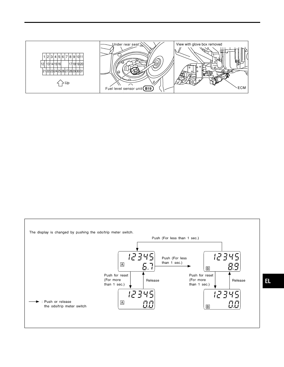
Location
NHEL0041
SEL550Y
System Description
NHEL0042
UNIFIED CONTROL METER
NHEL0042S06
I
Speedometer, odo/trip meter, tachometer, fuel gauge and water temperature gauge are controlled totally
by control unit built-in combination meter.
I
Digital meter is adopted for odo/trip meter.*
*The record of the odo meter is kept even if the battery cable is disconnected. The record of the trip meter
is erased when the battery cable is disconnected.
I
Odo/trip meter segment can be checked in diagnosis mode.
I
Meter/gauge can be checked in diagnosis mode.
HOW TO CHANGE THE DISPLAY FOR ODO/TRIP METER
NHEL0042S07
SEL175W
NOTE:
Turn ignition switch to the “ON” position to operate odo/trip meter.
GI
MA
EM
LC
EC
FE
AT
AX
SU
BR
ST
RS
BT
HA
SC
IDX
METERS AND GAUGES
Component Parts and Harness Connector Location
EL-125