Infiniti I35 (A33). Manual - part 384


  Index      Infiniti     Infiniti I35 (A33) - service repair manual 2004 year


Search            


Content   ..  382  383  384  385   ..


Infiniti I35 (A33). Manual - part 384


INSPECTION/FUEL LEVEL SENSOR UNIT

=NHEL0046S08

1

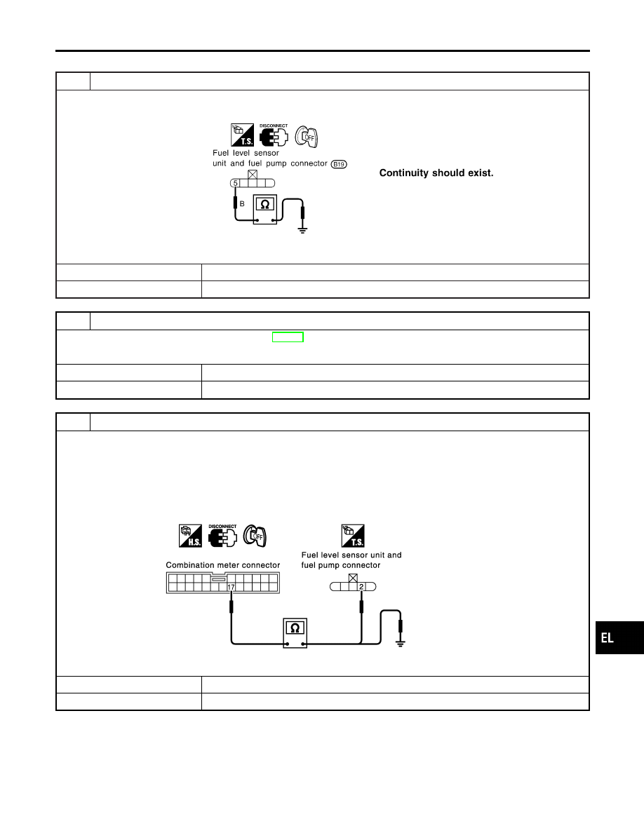
CHECK GROUND CIRCUIT FOR FUEL LEVEL SENSOR UNIT

Check harness continuity between fuel level sensor unit and fuel pump harness connector terminal 5 and ground.

SEL182W

OK or NG

OK

©

GO TO 2.

NG

©

Repair harness or connector.

2

CHECK FUEL LEVEL SENSOR UNIT

Refer to “FUEL LEVEL SENSOR UNIT CHECK” (EL-140).

OK or NG

OK

©

GO TO 3.

NG

©

Replace fuel level sensor unit.

3

CHECK HARNESS FOR OPEN OR SHORT

1. Disconnect combination meter connector and fuel level sensor unit and fuel pump connector.
2. Check continuity between combination meter harness connector M33 (with TCS) or M214 (with VDC) terminal 17 (G)

and fuel level sensor unit and fuel pump harness connector B19 terminal 2 (G).

Continuity should exist.

3. Check continuity between combination meter harness connector M33 (with TCS) or M214 (with VDC) terminal 17 (G)

and ground.

Continuity should not exist.

SEL183WA

OK or NG

OK

©

Fuel level sensor unit is OK.

NG

©

Repair harness or connector.

GI

MA

EM

LC

EC

FE

AT

AX

SU

BR

ST

RS

BT

HA

SC

IDX

METERS AND GAUGES

Trouble Diagnoses (Cont’d)

EL-137

INSPECTION/THERMAL TRANSMITTER

=NHEL0046S09

1

CHECK ECM OUTPUT

1. Disconnect combination meter.
2. Check voltage between combination meter harness connector M33 (with TCS) or M214 (with VDC) terminal 18 (PU/W)

and ground.

Battery voltage should exist.

SEL413Y

OK or NG

OK

©

GO TO 2.

NG

©

Replace.

2

CHECK HARNESS FOR OPEN OR SHORT

1. Disconnect combination meter connector and ECM connector.
2. Check continuity between combination meter harness connector M33 (with TCS) or M214 (with VDC) terminal 18

(PU/W) and ECM terminal 18 (PU/W).
Continuity should exist.

3. Check continuity between combination meter harness connector M33 (with TCS) or M214 (with VDC) terminal 18

(PU/W) and ground.
Continuity should not exist.

SEL417Y

OK or NG

OK

©

Thermal transmitter is OK.

NG

©

Repair harness or connector.

METERS AND GAUGES

Trouble Diagnoses (Cont’d)

EL-138

3

CHECK WATER TEMPERATURE OUTPUT SIGNAL

1. Connect combination meter connector and ECM connector.
2. Start engine.
3. Check output signal between combination meter harness connector M33 (with TCS) or M214 (with VDC) terminal 18

(PU/W) and ground. (Use “SIMPLE OSCILLOSCOPE” in “SUB MODE” with CONSULT-II.)

SEL414Y

OK or NG

OK

©

Replace combination meter.

NG

©

Check ECM.

GI

MA

EM

LC

EC

FE

AT

AX

SU

BR

ST

RS

BT

HA

SC

IDX

METERS AND GAUGES

Trouble Diagnoses (Cont’d)

EL-139

MEL372K

Electrical Components Inspection

=NHEL0047

FUEL LEVEL SENSOR UNIT CHECK

NHEL0047S01

I

For removal, refer to FE-6, “REMOVAL”.

Check the resistance between terminals 2 and 5.

Ohmmeter

Float position

mm (in)

Resistance

value

(+)

(−)

2

5

*1

Full

158 (6.22)

Approx. 4.5 - 5.5

*2

1/2

89.7 (3.531)

31.5 - 33.5

*3

Empty

22.1 (0.870)

80.0 - 80.3

*1 and *3: When float rod is in contact with stopper.

CEL219AA

VEHICLE SPEED SENSOR SIGNAL CHECK

NHEL0047S03

1.

Remove vehicle speed sensor from transmission.

2.

Turn vehicle speed sensor pinion quickly and measure voltage
across 1 and 2.

METERS AND GAUGES

Electrical Components Inspection

EL-140


Content   ..  382  383  384  385   ..