Infiniti I35 (A33). Manual - part 326
Wiring Diagram
NHEC1282
MEC370E
GI
MA
EM
LC
FE
AT
AX
SU
BR
ST
RS
BT
HA
SC
EL
IDX
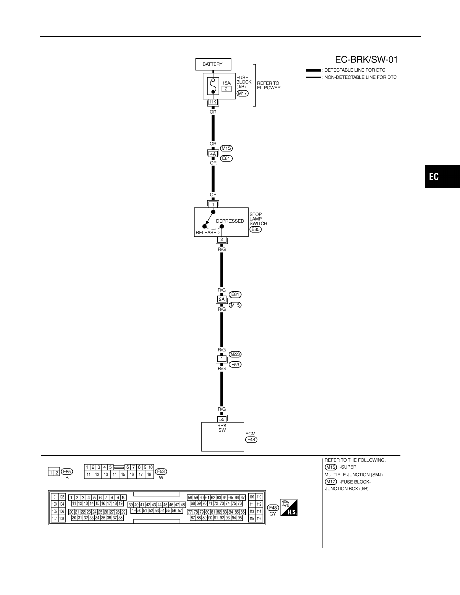
DTC P1805 BRAKE SWITCH
Wiring Diagram
EC-645
|
|
|
Wiring Diagram NHEC1282 MEC370E GI MA EM LC FE AT AX SU BR ST RS BT HA SC EL IDX DTC P1805 BRAKE SWITCH Wiring Diagram EC-645 |