Infiniti I35 (A33). Manual - part 324


  Index      Infiniti     Infiniti I35 (A33) - service repair manual 2004 year


Search            


Content   ..  322  323  324  325   ..


Infiniti I35 (A33). Manual - part 324


Diagnostic Procedure

NHEC1141

1

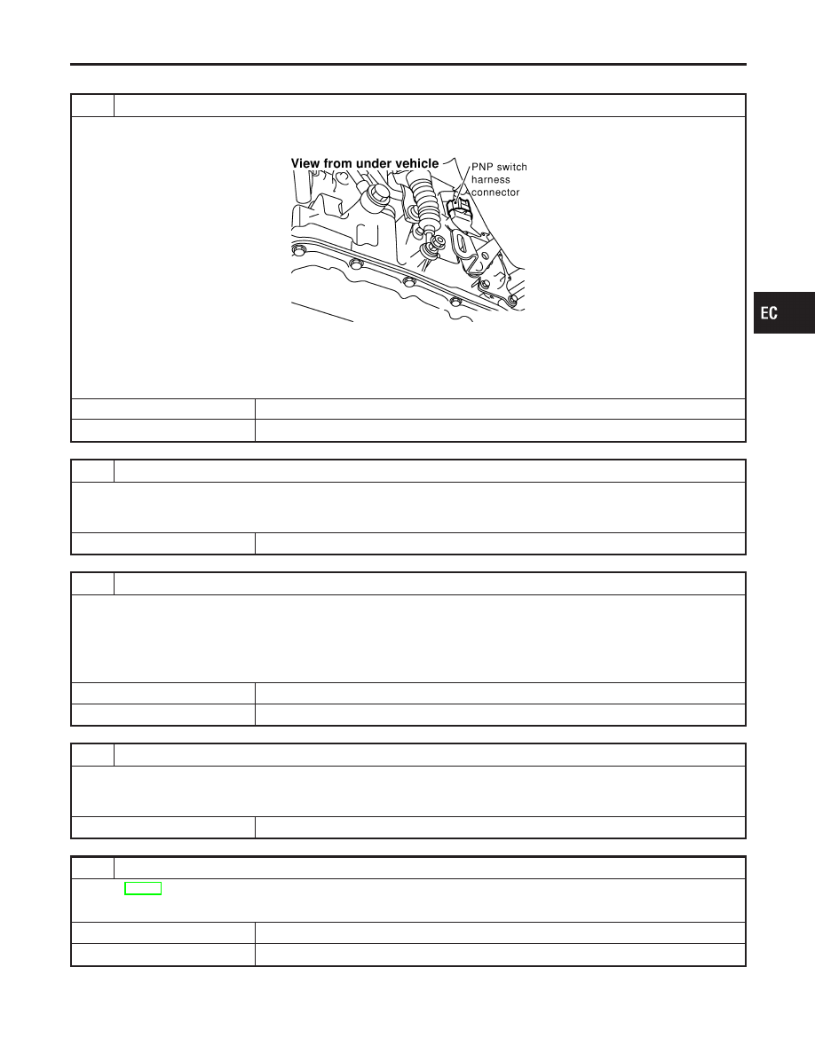
CHECK PNP SWITCH GROUND CIRCUIT FOR OPEN AND SHORT

1. Turn ignition switch OFF.
2. Disconnect park/neutral position (PNP) switch harness connector.

SEF279X

3. Check harness continuity between PNP switch terminal 2 and ground. Refer to Wiring Diagram.

Continuity should exist.

4. Also check harness for short to power.

OK or NG

OK

©

GO TO 3.

NG

©

GO TO 2.

2

DETECT MALFUNCTIONING PART

Check the following.

I

Harness connectors F93, F10

I

Check harness for open between park/neutral position (PNP) switch and ground.

©

Repair open circuit or short to power in harness or connectors.

3

CHECK PNP SWITCH INPUT SIGNAL CIRCUIT FOR OPEN AND SHORT

1. Disconnect ECM harness connector.
2. Check harness continuity between ECM terminal 44 and PNP switch terminal 1. Refer to Wiring Diagram.

Continuity should exist.

3. Also check harness for short to ground and short to power.

OK or NG

OK

©

GO TO 5.

NG

©

GO TO 4.

4

DETECT MALFUNCTIONING PART

Check the following.

I

Harness connectors F10, F93

I

Harness for open or short between ECM and park/neutral position (PNP) switch

©

Repair open circuit or short to ground or short to power in harness or connectors.

5

CHECK PARK/NEUTRAL POSITION (PNP) SWITCH

Refer to AT-111, “Diagnostic Procedure”.

OK or NG

OK

©

GO TO 6.

NG

©

Replace park/neutral position (PNP) switch.

GI

MA

EM

LC

FE

AT

AX

SU

BR

ST

RS

BT

HA

SC

EL

IDX

DTC P1706 PNP SWITCH

Diagnostic Procedure

EC-637

6

CHECK INTERMITTENT INCIDENT

Refer to “TROUBLE DIGNOSIS FOR INTERMITTENT INCIDENT”, EC-152.

©

INSPECTION END

DTC P1706 PNP SWITCH

Diagnostic Procedure (Cont’d)

EC-638

SEC058D

Component Description

NHEC1400

The VIAS control solenoid valve cuts the intake manifold vacuum
signal for power valve control. It responds to ON/OFF signals from
the ECM. When the solenoid is off, the vacuum signal from the
intake manifold is cut. When the ECM sends an ON signal the coil
pulls the plunger downward and feeds the vacuum signal to the
power valve actuator.

CONSULT-II Reference Value in Data Monitor
Mode

NHEC1404

MONITOR ITEM

CONDITION

SPECIFICATION

VIAS S/V

I

Engine: After warming up

1,800 - 3,600 rpm

ON

Except above condition

OFF

On Board Diagnosis Logic

NHEC1472

The MIL will not light up for this self-diagnosis.

DTC No.

Trouble diagnosis name

DTC Detecting Condition

Possible Cause

P1800
1800

VIAS control solenoid valve circuit
open

An improper voltage signal is sent to
ECM through VIAS control solenoid
valve.

I

Harness connectors
(The solenoid valve circuit is open
or shorted.)

I

VIAS control solenoid valve

DTC Confirmation Procedure

NHEC1473

NOTE:
If DTC Confirmation Procedure has been previously conducted,
always turn ignition switch OFF and wait at least 10 seconds before
conducting the next test.
TESTING CONDITION:
Before performing the following procedure, confirm battery
voltage is more than 11V at idle.

SEF058Y

WITH CONSULT-II

1.

Turn ignition switch ON.

2.

Select “DATA MONITOR” mode with CONSULT-II.

3.

Start engine and let it for 10 seconds.

4.

If 1st trip DTC is detected, go to “Diagnostic Procedure”,
EC-642.

GI

MA

EM

LC

FE

AT

AX

SU

BR

ST

RS

BT

HA

SC

EL

IDX

DTC P1800 VIAS CONTROL SOLENOID VALVE

Component Description

EC-639

WITH GST

Follow the procedure “WITH CONSULT-II” above.

DTC P1800 VIAS CONTROL SOLENOID VALVE

DTC Confirmation Procedure (Cont’d)

EC-640


Content   ..  322  323  324  325   ..