Honda Ridgeline. Manual - part 561
02
01
−
−
−
−
YES
NO
YES
NO
24-69
07XAZ-SZ30100
07SAZ-TB4011A
A
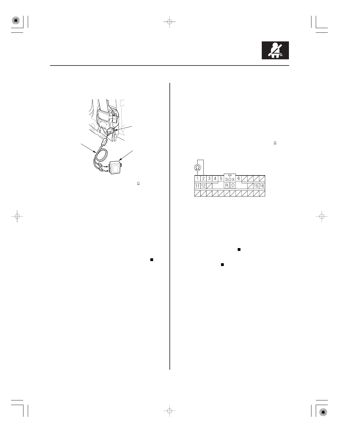
SRS UNIT CONNECTOR B (28P)
4. Disconnect the floor wire harness 4P connector (A)
from the driver’s seat belt tensioner.
5. Connect the SRS inflator simulator (2
connectors) and simulator lead F to the floor wire
harness.
6. Reconnect the negative cable to the battery.
7. Clear the DTC memory.
8. Read the DTC (see page 24-27).
Go to step 9.
Short in the driver’s seat belt tensioner;
replace the driver’s seat belt (see page 24-4).
9. Turn the ignition switch OFF. Disconnect the
negative cable from the battery, and wait for 3
minutes.
10. Disconnect the front passenger’s seat belt
tensioner connector (see step 6 on page 24-26).
11. Disconnect SRS unit connector B (28P) from the
SRS unit (see step 7 on page 24-26).
12. Disconnect the simulator lead from the floor wire
harness.
13. Measure the resistance between the No. 1 and the
No. 2 terminals of SRS unit connector B (28P).
There should be an open circuit or at least 1 M
.
Faulty SRS unit or poor connection at SRS
unit connector B (28P) and the SRS unit. Check the
connection; if the connection is OK, replace the
SRS unit (see page 24-188).
Short in the floor wire harness; replace the
floor wire harness.
Wire side of female terminals
Is DT C 21-3x indicated?
Is the r esistance as specif ied?