Honda Ridgeline. Manual - part 560
02
SJC8A00K791000R129XFAAT00
−
−
−
−
YES
NO
Special Tools Required
YES
NO
DTC 12-9x (‘‘x’’ can be 0 thru 9 or A thru F):
DTC 12-Bx (‘‘x’’ can be 0 thru 9 or A thru F):
24-65
24-65
07XAZ-SZ30100
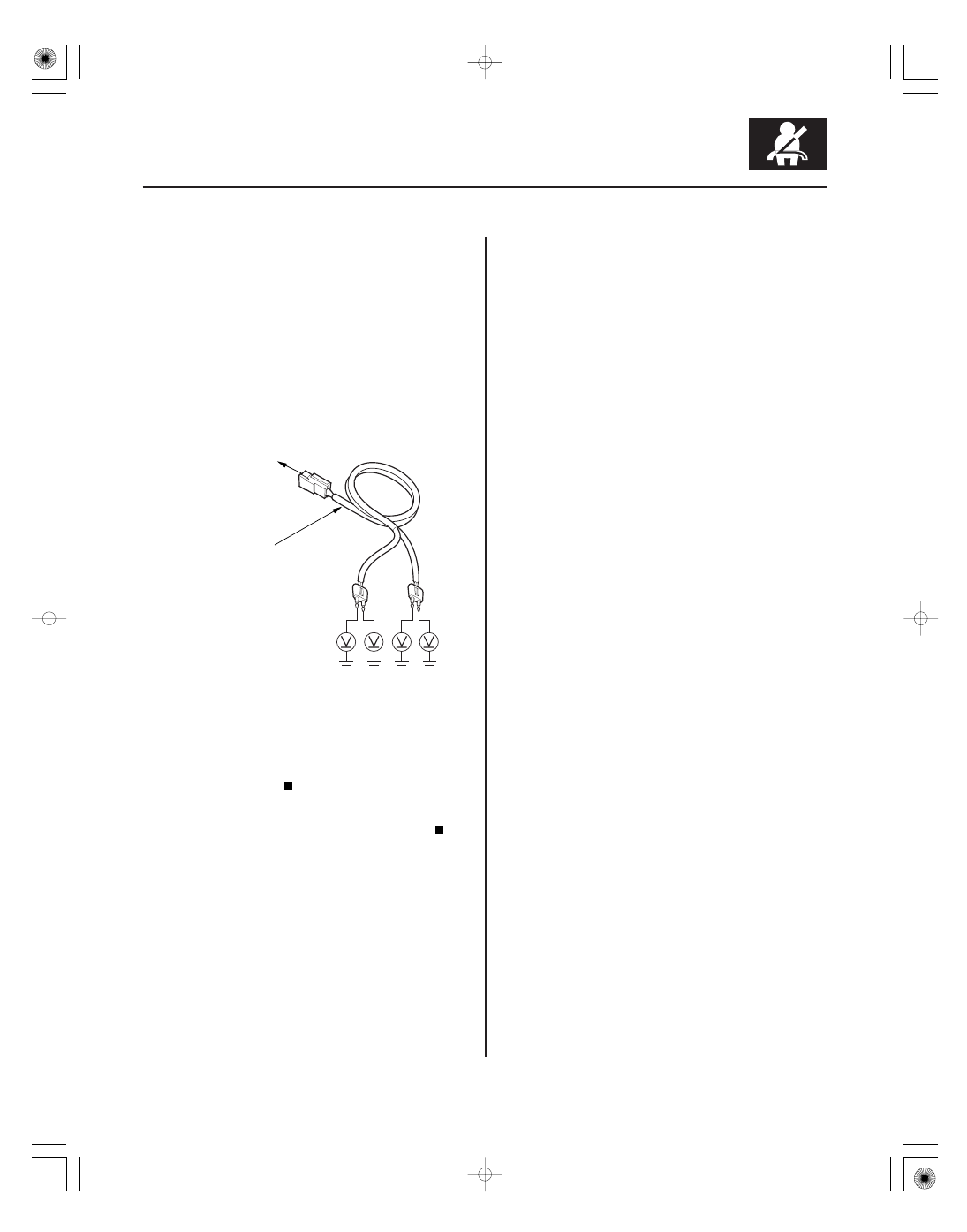
DASHBOARD
WIRE HARNESS
4P CONNECTOR
10. Disconnect SRS unit connector A (28P) from the
SRS unit (see step 7 on page 24-26).
11. Disconnect the SRS inflator simulator from the SRS
simulator lead.
12. Reconnect the negative cable to the battery.
13. Turn the ignition switch ON (II).
14. Measure the voltage between each terminal of both
SRS simulator leads and body ground. There
should be 0.5 V or less.
Faulty SRS unit or poor connection at SRS
unit connector A (28P) and the SRS unit. Check the
connection between the connector and the SRS
unit. If the connection is OK, replace the SRS unit
(see page 24-188).
Short to power in the dashboard wire
harness; replace the dashboard wire harness.
• SRS inflator simulator 07SAZ-TB4011A
• SRS simulator lead F 07XAZ-SZ30100
NOTE: Before doing this troubleshooting procedure,
review SRS Precautions and Procedures (see page
24-16) and General Troubleshooting Information
(see page 24-27).
1. Clear the DTC memory (see page 24-28).
2. Turn the ignition switch ON (II), and check that the
SRS indicator comes on for about 6 seconds and
then goes off.
Go to step 3.
Intermittent failure, the system is OK at this
time. Go to Troubleshooting Intermittent Failures
(see page 24-29). If another DTC is indicated,
troubleshoot the DTC.
3. Turn the ignition switch OFF. Disconnect the
negative cable from the battery, and wait for 3
minutes.
(cont’d)
Short to Ground in Front Passenger’s Airbag
First Inflator
Short to Ground in Front Passenger’s Airbag
Second Inflator
Is the voltage as specif ied?
Does the SRS indicator stay on, and is DT C 12-9x
or 12-Bx indicated?