Honda Ridgeline. Manual - part 518
*12
*13
*14
−
−
−
−
−
−
YES
NO
YES
NO
YES
NO
23-38
Audio System
Symptom Troubleshooting (cont’d)
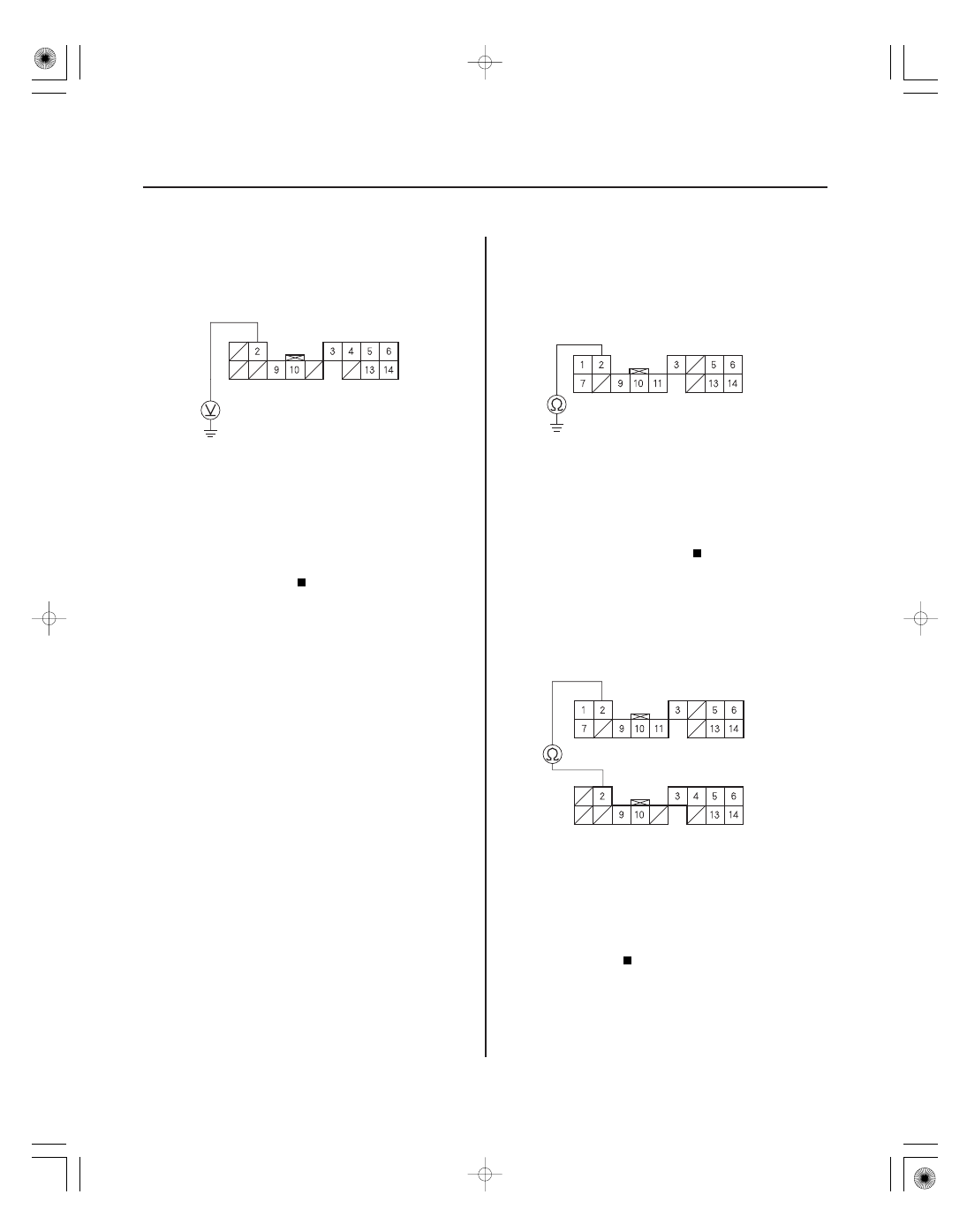
CD CHANGER CONNECTOR B (14P)
SAT SYSTEM ACC (ORN)
XM RECEIVER CONNECTOR A (14P)
SAT SYSTEM ACC(ORN)
XM RECEIVER CONNECTOR A (14P)
CD CHANGER CONNECTOR B (14P)
SAT SYSTEM ACC (ORN)
SAT SYSTEM ACC (ORN)
14. Measure the voltage between CD changer
connector B (14P) No. 2 terminal and body ground.
Go to step 15.
Substitute a known-good CD changer and
recheck. If 0.5 V or less are present, replace the
original CD changer.
15. Turn the ignition switch OFF.
16. Disconnect CD changer connector B (14P) and XM
receiver connector A (14P).
17. Check for continuity between XM receiver
connector A (14P) No. 2 terminal and body ground.
Repair short in the wire between the CD
changer and the XM receiver, or replace the
appropriate shielded harness.
Go to step 18.
18. Check for continuity between XM receiver
connector A (14P) No. 2 terminal and CD changer
connector B (14P) No. 2 terminal.
Go to step 19.
Repair open in the wire between CD changer
and XM receiver.
Wire side of female terminals
Wire side of female terminals
Wire side of female terminals
Wire side of female terminals
Is ther e less than 0.5 V ?
Is ther e continuity?
Is ther e continuity?