Honda Ridgeline. Manual - part 517


  Index      Honda     Honda Ridgeline - service repair manual 2006-2008 year


Search            


Content   ..  515  516  517  518   ..


Honda Ridgeline. Manual - part 517


*05

*06

*07

*08

XM receiver

connector

CD changer

connector

Wire color

YES

NO

CD changer connector

Wire color

YES

NO

CD changer

connector

Audio unit

connector

Wire color

YES

NO

23-34

Audio System

Symptom Troubleshooting (cont’d)

XM RECEIVER CONNECTOR A (14P)

CD CHANGER CONNECTOR A

CD CHANGER CONNECTOR A

AUDIO UNIT CONNECTOR B (14P)

10. Check for continuity between XM receiver

connector A (14P) and CD changer connector B
(14P) according to the table.

A6

B6

RED

A14

B14

GRN

A5

B5

WHT

A13

B13

BLK

A2

B2

ORN

Go to step 11.

Repair open in the wire between CD changer

and XM receiver.

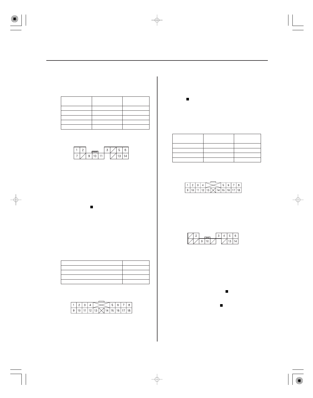
11. Disconnect CD changer connector A (18P) and

audio unit connector B (14P).

12. Check for continuity between CD changer

connector A (18P) and body ground according to
the table.
Check for continuity between the same terminals
listed in the table and the XM receiver connector A
(18P) No. 11 terminal (the harness shield).

A9

GRN

A1

WHT

A10

BLK

A2

RED

Repair short between the CD changer and the

audio unit, or replace the appropriate shield
harness.

Go to step 13.

13. Check for continuity between the CD changer

connector A (18P) and audio unit connector B (14P)
according to the table.

A9

B6

GRN

A1

B14

WHT

A10

B5

BLK

A2

B13

RED

Substitute a known-good XM receiver and

retest. If the symptom/indicated goes away replace
XM receiver. If the symptom/indicated is still
present replace the audio unit.

Repair open in the wire between the CD

changer and the audio unit.

Wire side of female terminals

Terminal side of female terminals

Terminal side of female terminals

Terminal side of female terminals

Is ther e continuity?

Is ther e continuity?

Is ther e continuity?

01

02

03

SJC8AN3J10300000000FAAT13

XM radio display is blank and no station
information is displayed

YES

NO

YES

NO

YES

NO

YES

NO

23-35

XM RECEIVER CONNECTOR A (14P)

B RADIO

(WHT/RED)

B RADIO (WHT/RED)

XM RECEIVER CONNECTOR A (14P)

GND (BLK)

AUDIO UNIT CONNECTOR B (14P)

SAT SYSTEM ACC (ORN)

NOTE:

• Check the vehicle battery condition first.
• Do not do this procedure if the CD changer and

navigation display buttons are inoperative. Refer to
the navigation system troubleshooting.

1. Check fuse No. 7 (7.5 A) in the under-dash fuse/

relay box.

Go to step 2.

Replace the fuse, and recheck.

2. Turn the ignition switch ON (II).

3. Measure the voltage between XM receiver

connector A (14P) No. 1 and No. 7 terminals and
body ground.

Go to step 4.

Repair open in the wire between fuse No. 7

(7.5 A) under-dash fuse/relay box and XM receiver
connector A (14P) No. 1 and No. 7 terminals.

4. Measure the voltage between XM receiver

connector A (14P) No. 11 terminal and body ground.

• With navigation: Go to step 12.
• Without navigation: Go to step 5.

Repair open in the wire between XM receiver

connector A (14P) No. 11 terminal and body ground
(G501).

5. Turn the ignition switch ON (II).

6. Measure the voltage between audio unit connector

B (14P) No. 2 terminal and body ground.

Go to step 7.

Go to step 9.

(cont’d)

Wire side of female terminals

Wire side of female terminals

Wire side of female terminals

Is the f use OK ?

Is ther e batter y voltage?

Is ther e less than 0.1 V ?

Is ther e 10 V or mor e pr esent?

04

*09

YES

NO

XM receiver connector

Wire color

YES

NO

23-36

Audio System

Symptom Troubleshooting (cont’d)

AUDIO UNIT CONNECTOR B (14P)

SAT SYSTEM ACC (ORN)

XM RECEIVER CONNECTOR A (14P)

7. Measure the voltage between audio unit connector

B (14P) No. 2 terminal and body ground.

Go to step 8.

Substitute a known-good audio unit and

recheck. If less than 0.5 V is present, replace the
original audio unit.

8. Turn the ignition switch OFF.

9. Disconnect audio unit connector B (14P) and XM

receiver connector A (14P).

10. Check for continuity between XM receiver

connector A (14P) and body ground according to
the table. Then check for continuity between the
same terminals listed in the table and XM receiver
connector A (14P) No. 3 terminal (the harness
shield).

A9

BLU

A10

PNK

A2

ORN

Repair short in the wire between the audio

unit and the XM receiver, or replace the
appropriate shielded harness.

Go to step 11.

Wire side of female terminals

Wire side of female terminals

Is ther e less than 0.5 V ?

Is ther e continuity?

*10

*11

05

XM receiver

connector

Audio unit

connector

Wire color

YES

NO

YES

NO

23-37

XM RECEIVER CONNECTOR A (14P)

AUDIO UNIT CONNECTOR B (14P)

AUDIO UNIT CONNECTOR B (14P)

SAT SYSTEM ACC (ORN)

11. Check for continuity between XM receiver

connector A (14P) and audio unit connector B (14P)
according to the table.

A9

B9

BLU

A10

B10

PNK

A2

B2

ORN

Substitute a known-good XM receiver, then

reconnect all the connectors and recheck. If the
symptom/indication goes away, replace the
original XM receiver. If symptom/indication is still
present, replace the audio unit.

Repair open in the wire between audio unit

and XM receiver.

12. Turn the ignition switch ON (II).

13. Measure the voltage between CD changer

connector B (14P) No. 2 terminal and body ground.

Go to step 14.

Go to step 20.

(cont’d)

Wire side of female terminals

Wire side of female terminals

Wire side of female terminals

Is ther e continuity?

Is ther e 10 V or mor e pr esent?


Content   ..  515  516  517  518   ..