Honda Ridgeline. Manual - part 483


  Index      Honda     Honda Ridgeline - service repair manual 2006-2008 year


Search            


Content   ..  481  482  483  484   ..


Honda Ridgeline. Manual - part 483


01

SJC8A00K782000Y1076FAAT10

DTC B1076:

YES

NO

YES

NO

YES

NO

YES

NO

22-228

Wipers/Washers

DTC Troubleshooting

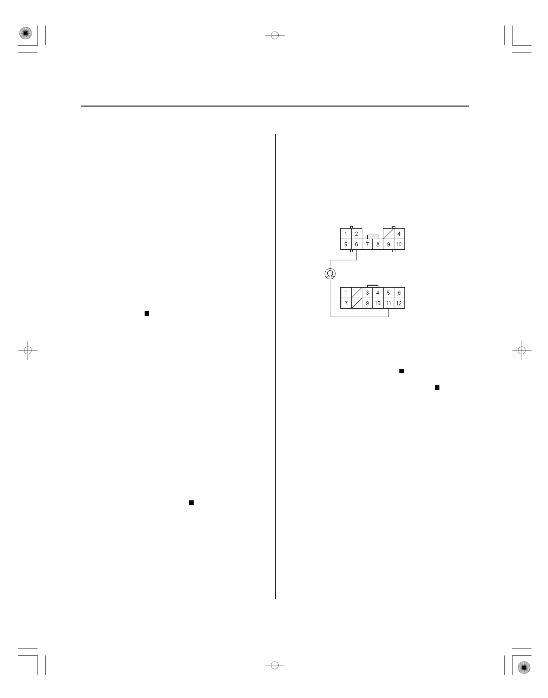
UNDER-HOOD FUSE/RELAY BOX CONNECTOR J (10P)

FR WIPER BACKUP
(GRN/WHT)

COMBINATION SWITCH 12P CONNECTOR

Windshield Wiper Signal Error

NOTE: If you are troubleshooting multiple DTCs, be
sure to follow the instructions in B-CAN System
Diagnosis Test Mode A (see page 22-99).

1. Clear the DTCs with the HDS.

2. Turn the ignition switch OFF, and then back ON (II).

3. Turn the wiper switch to INT, LOW, then HIGH for at

least 2 seconds each.

4. Check for DTCs with the HDS.

Go to step 5.

Intermittent failure. The windshield wiper

system is OK at this time. Check for loose or poor
connections.

5. With the wiper/washer switch OFF, select

WINDSHIELD WIPERS from the BODY ELECTRICAL
SYSTEM SELECT menu, and enter the DATA LIST.

6. Check the ON/OFF information of the WINDSHIELD

WIPER SWITCH (BACK-UP) in the DATA LIST.

Go to step 7.

Go to step 11.

7. Turn the wiper switch ON (low or high).

8. Check the ON/OFF information of the WINDSHIELD

WIPER SWITCH (BACK-UP) in the DATA LIST.

Faulty relay control module; replace the

under-hood fuse/relay box.

Go to step 9.

9. Disconnect the under-hood fuse/relay box

connector J (10P) and the combination switch 12P
connector.

10. Check for continuity between the No. 6 terminal of

the under-hood fuse/relay box connector J (10P)
and the No. 11 terminal of the combination switch
(combination switch control unit) 12P connector.

Faulty combination switch control unit;

replace the combination switch.

Repair an open in the GRN/WHT wire.

Wire side of female terminals

Wire side of female terminals

Is DT C B107 6 indicated?

Is the inf or mation indicator OF F ?

Is the inf or mation indicator ON?

Is ther e continuity?

02

03

YES

NO

YES

NO

22-229

UNDER-HOOD FUSE/RELAY BOX CONNETOR J (10P)

FR WIPER BACKUP
(GRN/WHT)

UNDER-HOOD FUSE/RELAY BOX CONNETOR J (10P)

FR WIPER BACKUP
(GRN/WHT)

11. Disconnect under-hood fuse/relay box connector J

(10P).

12. Check for continuity between the No. 6 terminal of

under-hood fuse/relay box connector J (10P) and
body ground.

Go to step 13.

Faulty relay control module; replace the

under-hood fuse/relay box.

13. Disconnect the combination switch 12P connector.

14. Check for continuity between the No. 6 terminal of

under-hood fuse/relay box connector J (10P) and
body ground.

Repair a short in the GRN/WHT wire.

The combination switch control unit is faulty;

replace the combination switch.

Wire side of female terminals

Wire side of female terminals

Is ther e continuity?

Is ther e continuity?

*01

02

SJC8A00K782000Y1077FAAT00

DTC B1077:

YES

NO

YES

NO

YES

NO

YES

NO

YES

NO

22-230

Wipers/Washers

DTC Troubleshooting (cont’d)

UNDER-HOOD FUSE/RELAY BOX CONNECTOR K (5P)

WHT

WINDSHIELD WIPER MOTOR 5P CONNECTOR

WHT

UNDER-HOOD FUSE/RELAY BOX CONNECTOR K (5P)

WHT

Windshield Wiper (As) Signal

Error

NOTE: If you are troubleshooting multiple DTCs, be
sure to follow the instructions in B-CAN System
Diagnosis Test Mode A (see page 22-99).

1. Clear the DTCs with the HDS.

2. Turn the ignition switch OFF, and then back ON (II).

3. Turn the wiper switch to LOW, then HIGH for at

least 15 seconds in each position.

4. Check for DTCs with the HDS.

Go to step 5.

Intermittent failure. The windshield wiper

system is OK at this time. Check for loose or poor
connections.

5. Turn the ignition switch OFF.

6. Do the wiper motor test (see page 22-235).

Go to step 7.

Replace the windshield wiper motor and

recheck.

7. Turn the ignition switch ON (II).

8. Turn the wiper switch to LOW, then HIGH and

check wiper operation.

Go to step 9.

Go to step 12.

9. Disconnect under-hood fuse/relay box connector K

(5P) and the windshield wiper motor 5P connector.

10. Check for continuity between the No. 4 terminal of

the windshield wiper motor 5P connector and No. 2
terminal of under-hood fuse/relay box connector K
(5P).

Go to step 11.

Repair an open in the WHT wire.

11. Check for continuity between the No. 2 terminal of

under-hood fuse/relay box connector K (5P) and
body ground.

Repair a short in the WHT wire.

Faulty relay control module; replace the

under-hood fuse/relay box.

Wire side of female terminals

Wire side of female terminals

Wire side of female terminals

Is DT C B107 7 indicated?

Does the wiper motor oper ate cor r ectly?

Do the wiper s oper ate nor mally?

Is ther e continuity?

Is ther e continuity?

03

*02

YES

NO

YES

NO

YES

NO

22-231

GRN

WINDSHIELD WIPER MOTOR 5P CONNECTOR

UNDER-HOOD FUSE/RELAY BOX CONNECTOR K (5P)

BLU

WINDSHIELD WIPER MOTOR 5P CONNECTOR

YEL

BLU

YEL

12. Turn the ignition switch OFF.

13. Check the No. 11 (30 A) fuse in the under-dash fuse/

relay box.

Go to step 14.

Replace the blown fuse and recheck the

system. If the fuse is blown again, check for a short
on the GRN wire between the under-dash fuse/
relay box and the windshield wiper motor.

14. Turn the ignition switch ON (II).

15. Measure voltage between the No. 1 terminal of the

windshield wiper motor 5P connector and body
ground.

Go to step 16.

Repair an open in the GRN wire.

16. Check for continuity between the No. 3 and No. 5

terminals of the windshield wiper motor 5P
connector and the No. 1 and No. 3 terminals of
under-hood fuse/relay box connector K (5P).

Faulty relay control module; replace the

under-hood fuse/relay box.

Repair an open in the BLU or YEL wire.

Wire side of female terminals

Wire side of female terminals

Wire side of female terminals

Is the f use OK ?

Is ther e batter y voltage?

Is ther e continuity?


Content   ..  481  482  483  484   ..