Honda Ridgeline. Manual - part 462


  Index      Honda     Honda Ridgeline - service repair manual 2006-2008 year


Search            


Content   ..  460  461  462  463   ..


Honda Ridgeline. Manual - part 462


03

Door Multiplex Control Unit

Cavity

Wire

Test condition

Test: Desired result

Possible cause if result is not obtained

22-144

Keyless/Power Door Locks/Security System

Control Unit Input Test (cont’d)

WHT/BLK

WHT

YEL

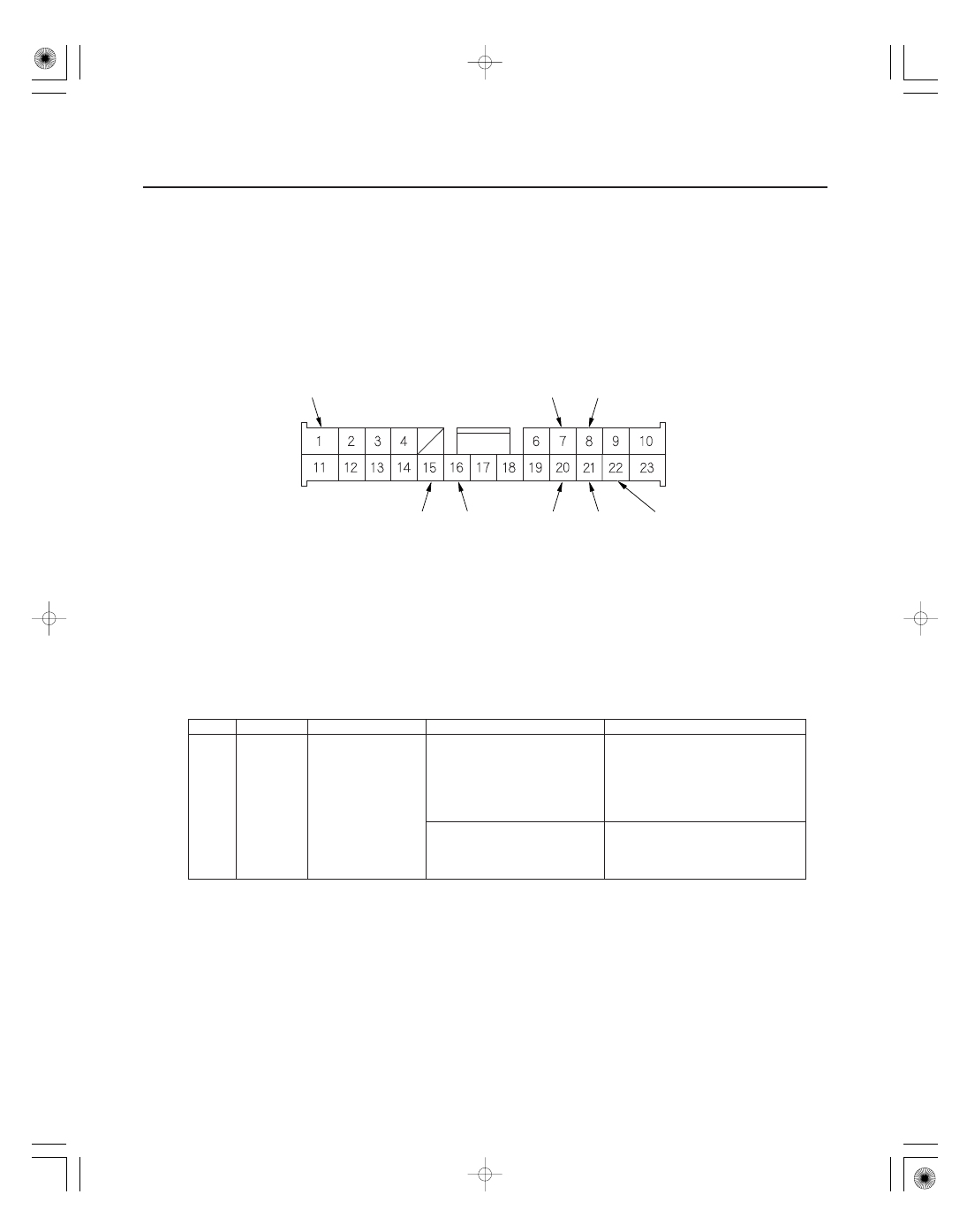
DOOR MULTIPLEX CONTROL UNIT CONNECTOR (23P)

WHT/RED

YEL/RED

BRN/BLK

WHT/RED

BLK

13. Turn the ignition switch OFF.

14. Remove the power window master switch (see page 22-221).

15. Disconnect the 23P connector from the power window master switch.

16. Inspect the connector and socket terminals to be sure they are all making good contact.

• If the terminals are bent, loose or corroded, repair them as necessary, and recheck the system.
• If the terminals look OK, go to step 17.

17. With the connector still disconnected, make these input tests at the connector.

• If the test indicates a problem, find and correct the cause, then recheck the system.
• If the input tests prove OK, go to step 18.

16

BRN/BLK

Under all
conditions

Check for continuity between
the No. 16 terminal and
under-dash fuse/relay box
connector J (21P) No. 4
terminal:
There should be continuity.

An open in the wire

Check for continuity between
the No. 16 terminal and body
ground:
There should be no continuity.

A short in the wire

Wire side of female terminals

Cavity

Wire

Test condition

Test: Desired result

Possible cause if result is not obtained

22-145

18. Reconnect the connector to the door multiplex control unit. Turn the ignition switch ON (II) and make these input

tests at the connectors.

• If any test indicates a problem, find and correct the cause, then recheck the system.
• If all the input tests prove OK, go to step 19.


1

BLK

Under all
conditions

Check for voltage to ground:
There should be less than 0.5 V.

Poor ground (G501)
An open in the wire

15

WHT/RED

Under all
conditions

Check for voltage to ground:
There should be battery voltage.

Blown No. 7 (7.5 A) fuse in the
under-dash fuse/relay box.
An open in the wire

20

YEL

Ignition switch
ON (II)

Check for voltage to ground:
There should be battery voltage.

Blown No. 21 (7.5 A) fuse in the
under-dash fuse/relay box.
An open in the wire

7

WHT/BLK

Driver’s door
lock knob switch
unlocked

Check for voltage to ground:
There should be less than 1 V.

Poor ground (G401)
Faulty driver’s door lock knob
switch
An open in the wire

Driver’s door
lock knob switch
locked

Check for voltage to ground:
There should be 5 V or more.

Faulty driver’s door lock knob
switch
Short to ground

22

YEL/RED

Driver’s door
lock knob switch
locked

Check for voltage to ground:
There should be less than 1 V.

Poor ground (G401)
Faulty driver’s door lock knob
switch
An open in the wire

Driver’s door
lock knob switch
unlocked

Check for voltage to ground:
There should be 5 V or more.

Faulty driver’s door lock knob
switch
Short to ground

8

WHT/RED

Driver’s door key
cylinder switch
in LOCK

Check for voltage to ground:
There should be less than 1 V.

Faulty driver’s door key cylinder
switch
Poor ground (G401)
An open in the wire

Driver’s door key
cylinder switch
in neutral

Check for voltage to ground:
There should be 5 V or more.

Short to ground
Faulty driver’s door key cylinder
switch

Driver’s door key
cylinder switch
in UNLOCK

Check for voltage to ground:
There should be 5 V or more.

21

WHT

Driver’s door key
cylinder switch
in UNLOCK

Check for voltage to ground:
There should be less than 1 V.

Faulty driver’s door key cylinder
switch
Poor ground (G401)
An open in the wire

Driver’s door key
cylinder switch
in neutral

Check for voltage to ground:
There should be 5 V or more.

Short to ground
Faulty driver’s door key cylinder
switch

Driver’s door key
cylinder switch
in LOCK

Check for voltage to ground:
There should be 5 V or more.

19. If all the input tests prove OK, and no DTCs were found during multiplex integrated control system

troubleshooting (B-CAN System Diagnostic Test Mode A) (see page 22-99), go to the B-CAN system input and
output index (see page 22-92). If multiple failures are found on more than one control unit, replace the under-dash
fuse/relay box (includes the MICU). If input failures are related to a particular control unit, replace that control unit.

01

02

03

04

SJC8A00J46660520901FEAT10

Driver’s door

Passenger’s door

22-146

Keyless/Power Door Locks/Security System

Door Lock Actuator Test

LOCK

UNLOCK

Terminal

Position

1

2

LOCK

UNLOCK

Terminal

Position

1

2

1. Remove the driver’s door panel (see page 20-7).

2. Disconnect the 2P connector from the actuator.

3. Check actuator operation by connecting power and

ground according to the table. To prevent damage
to the actuator, apply battery voltage only
momentarily.

4. If the actuator does not operate as specified,

replace it.

1. Remove the passenger’s door panel.

• Front door panel (see page 20-7)
• Rear door panel (see page 20-14)

2. Disconnect the 2P connector from the actuator.

3. Check actuator operation by connecting power and

ground according to the table. To prevent damage
to the actuator, apply battery voltage only
momentarily.

4. If the actuator does not operate as specified,

replace it.

01

02

SJC8A00J46660521011FEAT10

Driver’s Door

Front Passenger’s Door (RTS, RTL, and EXL
models)

22-147

Door Lock Knob Switch Test

Not used

1. Remove the driver’s door panel (see page 20-7).

2. Disconnect the 3P connector from the actuator.

3. Check for continuity between the terminals.

• There should be continuity between the No. 2

and No. 3 terminals when the door lock knob
switch is in the LOCK position and no continuity
when the switch is in the UNLOCK position.

• There should be continuity between the No. 1

and No. 3 terminals when the door lock knob
switch is in the UNLOCK position and no
continuity when the switch is in the LOCK
position.

4. If the continuity is not as specified, replace the door

lock actuator.

1. Remove the front passenger’s door panel (see page

20-7).

2. Disconnect the 3P connector from the actuator.

3. Check for continuity between the terminals.

There should be continuity between the No. 1 and
No. 3 terminals when the door lock knob switch in
the UNLOCK position and no continuity when the
switch is in the LOCK position.

4. If the continuity is not as specified, replace the door

lock actuator.

(cont’d)


Content   ..  460  461  462  463   ..