Honda Ridgeline. Manual - part 461
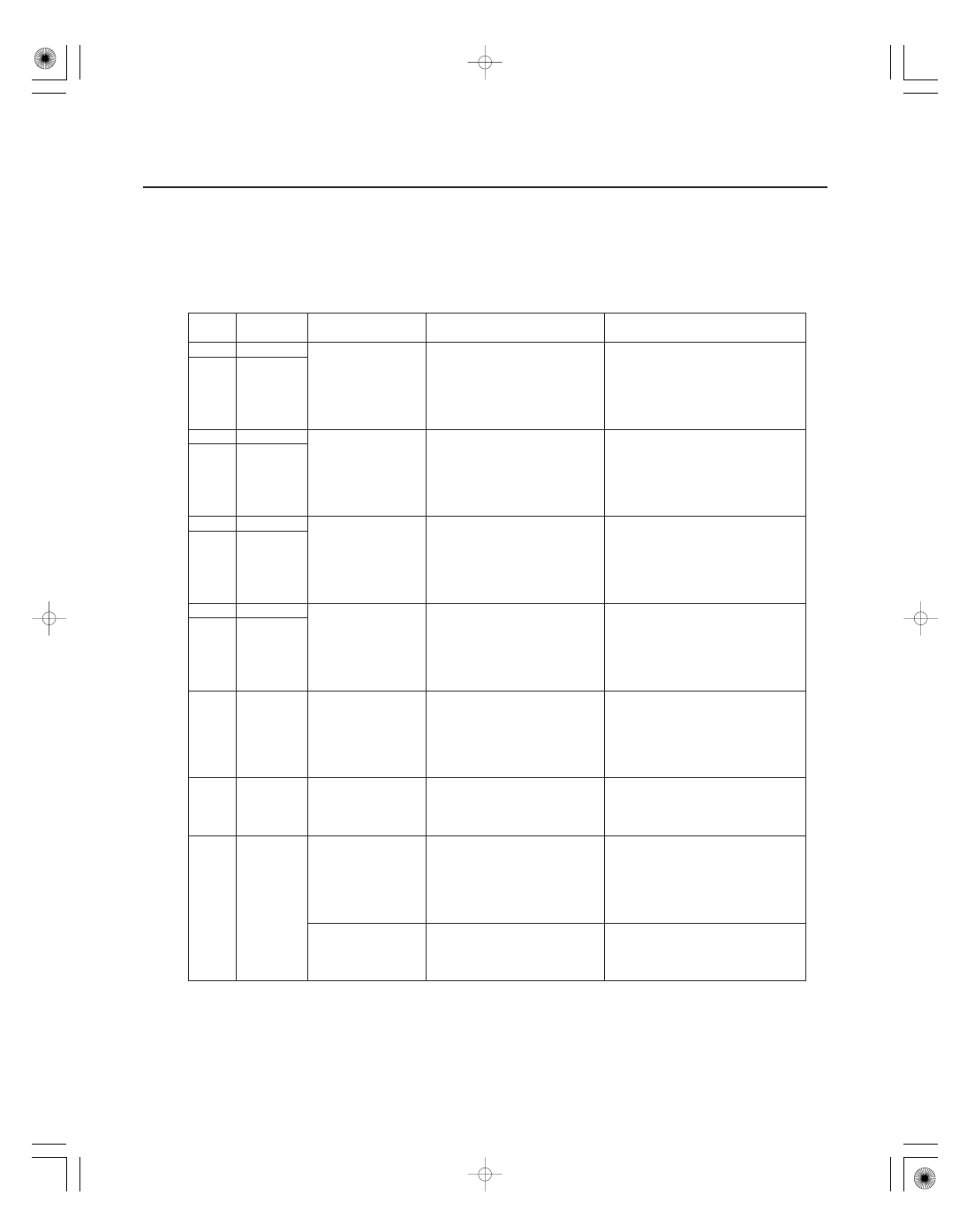
Cavity
Wire
Test condition
Test: Desired result
Possible cause if result is not
obtained
22-140
Keyless/Power Door Locks/Security System
Control Unit Input Test (cont’d)
5. With the connectors still disconnected, make these input tests at the connectors.
• If any test indicates a problem, find and correct the cause, then recheck the system.
• If the input tests prove OK, go to step 6.
•
•
•
•
•
•
•
•
•
•
•
•
•
•
•
K2
YEL/GRN
Connect the
battery positive
terminal to K12
(K2) terminal, and
K2 (K12) terminal
to H9 terminal
Check actuator operation:
The driver’s door lock
actuator should lock (unlock).
Faulty driver’s door lock
actuator
An open in the wire
K12
YEL/BLK
N7
YEL/BLK
Connect the
battery positive
terminal to N7 (N9)
terminal, and N9
(N7) terminal to H9
terminal
Check actuator operation:
The front passenger’s door
lock actuator should lock
(unlock).
Faulty front passenger’s door
lock actuator
An open in the wire
N9
YEL
H3
YEL/BLK
Connect the
battery positive
terminal to H3
(H10) terminal, and
H10 (H3) terminal
to H9 terminal
Check actuator operation:
The left rear door lock
actuator should lock (unlock).
Faulty left rear door lock
actuator
An open in the wire
H10
YEL
E2
YEL/BLK
Connect the
battery positive
terminal to E2 (E8)
terminal, and E8
(E2) terminal to H9
terminal
Check actuator operation:
The right rear door lock
actuator should lock (unlock).
Faulty right rear door lock
actuator
An open in the wire
E8
YEL
F5
RED/WHT
Connect the
battery positive
terminal to F5
terminal with the
trunk lid main
switch ON
Check actuator operation:
The in-bed trunk lid actuator
should unlock.
Poor ground (G601)
Faulty in-bed trunk lid main
switch
Faulty in-bed trunk lid actuator
An open in the wire
J14
BLK/YEL
Under all
conditions
Attach to ground:
The security indicator should
come on.
Blown No. 7 (7.5 A) fuse in the
under-dash fuse/relay box
Faulty security indicator
An open in the wire
N5
BLK/YEL
Under all
conditions
Check for continuity between
the N5 terminal and the
gauge control module
connector B (14P) No. 7
terminal:
There should be continuity.
An open in the wire
Gauge control
module connector
B (14P)
disconnected
Check for continuity to
ground:
There should be no continuity.
Short to ground