Honda Ridgeline. Manual - part 459
*01
−
−
−
−
−
22-132
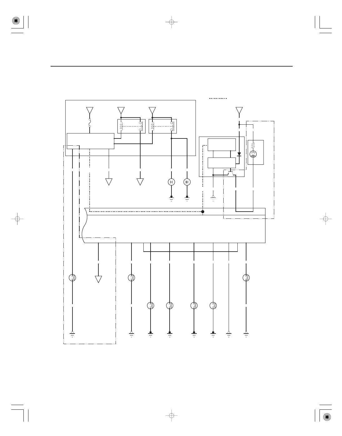
Keyless/Power Door Locks/Security System
Circuit Diagram (cont’d)
C
B
A
D
* :
RTS, RTL, and EXL models
: Communication line
MICU
BLK
G201
GRN/BLK
H2
BLK
G602
BLU/ORN
Q11
2
1
H13
GRN/WHT
E14
LT GRN/RED
H12
GRN/YEL
E15
GRN
2
1
P13
RED/WHT
G401
BLK
UNDER HOOD FUSE/RELAY BOX
G501
BLK
H9
2
1
RED/WHT
P27
•
•
*
No.15 (40 A) FUSE
J8
BLU
GRN/YEL
B CAN
RED/BLK
•
•
RELAY CONTROL MODULE
TAILLIGHTS
D11
B CAN
No.4 (15 A) FUSE
No.13 (20 A) FUSE
BLU/RED
BLU/RED
H9
H1
UNDER DASH FUSE/RELAY BOX
BRN/YEL
G602
BLK
BLK/YEL
GAUGE CONTROL MODULE
BLK/YEL
B6
A10
B7
N5
J14
(LED)
1
2
No.7 (7.5 A) FUSE
WHT/RED
WHT/RED
WHT/RED
A19
*
N28
J4
1
1
1
1
No.7
(7.5 A)
HOOD
SWITCH
(Closed :
Hood open)
TAILGATE
SWITCH
(Closed :
Tailgate open)
LEFT
REAR
DOOR
SWITCH
(Closed :
Door open)
FRONT
PASSENGER’S
DOOR
SWITCH
(Closed :
Door open)
DRIVER’S
DOOR
SWITCH
(Closed :
Door open)
IGNITION
KEY
SWITCH
(Closed :
Key inserted)
RIGHT
REAR
DOOR
SWITCH
(Closed :
Door open)
CD CHANGER
(With navigation
system)
AUDIO UNIT
(Without navigation
system)
HORN
SWITCH
FRONT PARKING
LIGHTS
TAILLIGHT
RELAY
CIRCUIT
HORN
RELAY
CIRCUIT
HORN
(High)
HORN
(Low)
CONTROLLER
AREA NETWORK
CONTROLLER
B CAN
TRANSCEIVER
SECURITY
INDICATOR