Honda Ridgeline. Manual - part 266
07
*01
04
*02
SJC8A00E44381000000FAAT06
−
−
−
−
−
−
The VTM-4 LOCK indicator does not come on
for about 4 seconds when the ignition switch
is turned ON (II)
YES
NO
YES
NO
YES
NO
15-46
Rear Differential
Symptom Troubleshooting (cont’d)
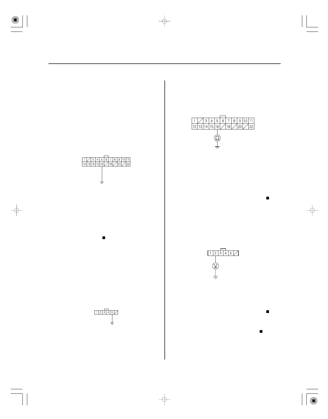
VTM-4 CONTROL UNIT CONNECTOR A (22P)
LOCKH
(YEL/BLK)
JUMPER WIRE
JUMPER WIRE
YEL/BLK
VTM-4 LOCK SWITCH 6P CONNECTOR
LOCKH (YEL/BLK)
VTM-4 CONTROL UNIT CONNECTOR A (22P)
YEL
VTM-4 LOCK SWITCH 6P CONNECTOR
1. Disconnect the VTM-4 control unit connector A
(22P).
2. Turn the ignition switch ON (II).
3. Connect the No. 16 terminal of the VTM-4 control
unit connector A (22P) to body ground with a
jumper wire.
4. Watch the VTM-4 LOCK indicator.
Check for poor connections or loose
terminals at the VTM-4 control unit connectors. If
the connections are OK, replace the VTM-4 control
unit (see page 15-50).
Go to step 5.
5. Turn the ignition switch OFF.
6. Remove the VTM-4 LOCK switch.
7. Connect the No. 5 terminal of the VTM-4 LOCK
switch 6P connector to body ground with a jumper
wire.
8. Check for continuity between the No. 16 terminal of
the VTM-4 conntrol unit connector A (22P) and
body ground.
Go to step 9.
Repair open in the wire between the VTM-4
control unit (A16) and the VTM-4 LOCK switch.
9. Turn the ignition switch ON (II).
10. Measure voltage between the No. 2 terminal of the
VTM-4 LOCK switch 6P connector and body ground.
Replace the VTM-4 LOCK indicator bulb.
Repair open in the wire between the No. 2
terminal of the VTM-4 LOCK switch 6P connector
and the driver’s under-dash fuse/relay box.
Wire side of female terminals
Wire side of female terminals
Wire side of female terminals
Wire side of female terminals
Does the V T M-4 LOCK indicator come on?
Is ther e continuity?
Is ther e batter y voltage?