Honda Ridgeline. Manual - part 253
−
−
−
07
08
−
−
−
Starting Torque:
1.15
1.71 N·m
(11.7
17.4 kgf·cm, 10.2
15.1 lbf·in.)
14-397
07XAB-0020100
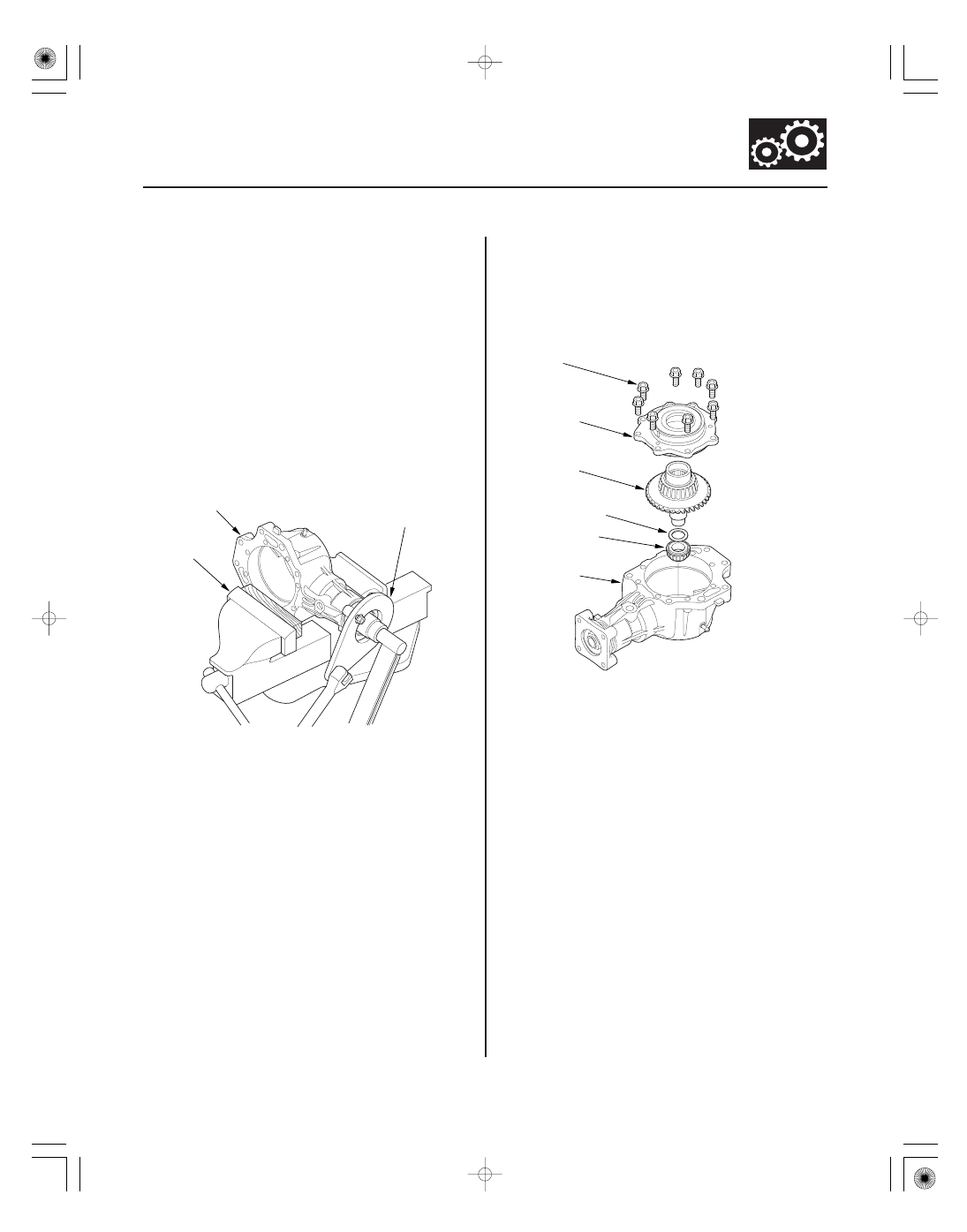
A
B
8 x 1.25 mm
26 N·m (2.7 kgf·m, 20 lbf·ft)
A
B
C
D
E
8. Secure the transfer housing (A) in a bench vise (B)
with soft jaws, then install the companion flange
holder on the companion flange. To prevent
damage to the transfer housing, always use soft
jaws or equivalent materials between the transfer
housing and the vise.
9. Tighten the locknut while measuring the starting
torque of the transfer output shaft (hypoid gear) so
the starting torque is within 1.15
1.71 N·m (11.7
17.4 kgf·cm, 10.2
15.1 lbf·in.).
NOTE: Do not stake the locknut in this step.
10. Apply Prussian Blue to both sides of the transfer
hypoid drive gear teeth lightly and evenly.
11. Install the tapered roller bearing (A), the 25 mm
thrust shim (B), and the transfer hypoid drive gear/
shaft assembly (C) in the transfer housing (D).
12. Install the transfer cover (E) and the bolts, and
tighten the bolts. Do not install the O-ring on the
transfer cover.
(cont’d)