Honda Ridgeline. Manual - part 252


  Index      Honda     Honda Ridgeline - service repair manual 2006-2008 year


Search            


Content   ..  250  251  252  253   ..


Honda Ridgeline. Manual - part 252


01

02

03

SJC8A00E10474559741KDAT00

Special Tools Required

14-393

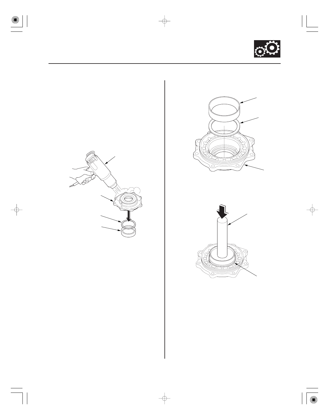
Transfer Cover Tapered Roller Bearing Outer Race Removal/Installation

A

B

C

D

B

A

C

07749-0010000

07NAD-PX40100

• Driver 07749-0010000
• Attachment, 78 x 80 mm 07NAD-PX40100

NOTE: Replace the bearing with a new one whenever
the outer race is replaced.

1. Remove the bearing outer race (A) and the 80 mm

thrust shim (B) from the transfer cover (C). If the
bearing outer race is press-fitted, remove the outer
race by heating the cover to about 212 °F (100 °C)
with a heat gun (D). Do not heat the cover more
than 212 °F (100 °C).

2. Install the 80 mm trust shim (A) and the bearing

outer race (B) in the transfer cover (C).

3. Drive the outer race securely in the cover with the

driver and attachment (78 x 80 mm), so there is no
clearance between the outer race, thrust shim, and
cover.

01

02

SJC8A00E10474559731KBAT00

Special Tools Required

14-394

Transfer Assembly

Transfer Cover Oil Seal Replacement

07749-001000

07JAD-SH30100

A

B

C

• Driver 07749-0010000
• Attachment, 65 mm 07JAD-SH30100

1. Remove the oil seal from the transfer cover.

2. Install the new oil seal (A) in the transfer cover (B)

to a height (C) of 0

1 mm (0

0.04 in.) above the

cover surface with the driver and attachment
(65 mm).

01

02

SJC8A00E10474500000LDAT00

??

Special Tools Required

THRUST SHIM, 40 mm

Shim

No.

Part Number

Thickness

14-395

Reassembly

FORMULA:

A:

B:

C:

Number on the replacement transfer output
shaft (hypoid gear)
Thickness of the existing 40 mm thrust shim

X: Thickness needed for the replacement 40 mm

thrust shim

NOTE: The number on the transfer output
shaft (hypoid gear) is shown in 1/100 mm.

100

A

100

B

C = X

Number on the existing transfer output
shaft (hypoid gear)

EXAMPLE:
C: EXISTING 40 mm

THRUST SHIM
Thickness: C=1.05 mm

X: REPLACEMENT 40 mm

THRUST SHIM
Thickness: X=

mm

A: EXISTING TRANSFER

OUTPUT SHAFT
(HYPOID GEAR)
Number: A=

2

B: REPLACEMENT

TRANSFER
OUTPUT SHAFT
(HYPOID GEAR)
Number: B=

1

Select No. M 40 mm thrust shim of 1.08 mm (0.043 in.).

100

A

100

B

C

X=

=

100

2

100

1

1.05

=0.02

0.01

1.05=1.08 (mm)

A

B

• Driver, 40 mm I.D. 07746-0030100
• Attachment, 35 mm I.D. 07746-0030400
• Driver 07749-0010000
• Oil seal driver attachment 07GAD-PG40100 or

07GAD-PG40101

• Companion flange holder 07XAB-0020100
• Attachment, 78 x 80 mm 07NAD-PX40100

NOTE:

• While reassembling the transfer assembly:

– Check and adjust the transfer gear tooth contact.
– Measure and adjust the transfer gear backlash.
– Check and adjust the tapered roller bearing starting

torque.

• Coat all parts with ATF during reassembly.
• Replace the tapered roller bearing and the bearing

outer race as a set if either part is replaced.

• Replace the transfer hypoid drive gear and the

transfer output shaft (hypoid gear) as a set if either
part is replaced.

1. Select the 40 mm thrust shim if the transfer output

shaft (hypoid gear) is replaced. Calculate the
thickness of the 40 mm thrust shim using the
formula below, and select the shim from the
following table.

A

29361-RDK-000

0.72 mm (0.028 in.)

B

29362-RDK-000

0.75 mm (0.030 in.)

C

29363-RDK-000

0.78 mm (0.031 in.)

D

29364-RDK-000

0.81 mm (0.032 in.)

E

29365-RDK-000

0.84 mm (0.033 in.)

F

29366-RDK-000

0.87 mm (0.034 in.)

G

29367-RDK-000

0.90 mm (0.035 in.)

H

29368-RDK-000

0.93 mm (0.037 in.)

I

29369-RDK-000

0.96 mm (0.038 in.)

J

29370-RDK-000

0.99 mm (0.039 in.)

K

29371-RDK-000

1.02 mm (0.040 in.)

L

29372-RDK-000

1.05 mm (0.041 in.)

M

29373-RDK-000

1.08 mm (0.043 in.)

N

29374-RDK-000

1.11 mm (0.044 in.)

O

29375-RDK-000

1.14 mm (0.045 in.)

2. Select the 40 mm thrust shim if the tapered roller

bearing on the transfer output shaft (hypoid gear) is
replaced. Measure the thickness of the replacement
bearing and the existing bearing, and calculate the
difference of the bearing thickness. Adjust the
thickness of the existing 40 mm thrust shim by the
amount of difference in bearing thickness, and
select the replacement 40 mm thrust shim.

(cont’d)

03

04

05

06

14-396

Transfer Assembly

Reassembly (cont’d)

07746-0030100

C

A

B

07749-0010000

07GAD-PG40100 or
07GAD-PG40101

B

A

B

D

A

C

3. Install the 40 mm thrust shim (A) on the transfer

output shaft (hypoid gear) (B), then install the
tapered roller bearing (C) with the driver (40 mm I.D.)
and a press.

4. Place the tapered roller bearing on the bearing

outer race of the companion flange side of the
transfer housing.

5. Install a new oil seal on the transfer housing with

the driver, oil seal driver attachment, and the press.

6. Install the transfer output shaft (hypoid gear) (A) in

the transfer housing (B). Do not install the thrust
washers and transfer spacer on the transfer output
shaft.

7. Install the companion flange (A), the conical spring

washer (B) in the direction shown, and the locknut
(C) on the transfer output shaft (hypoid gear) (D).
Do not install the O-ring and back-up ring on the
transfer output shaft.


Content   ..  250  251  252  253   ..