Honda Ridgeline. Manual - part 59
01
02
03
SJC8A00A14426149419FAAT00
−
−
−
−
−
−
−
−
−
−
YES
NO
YES
NO
YES
NO
YES
NO
YES
NO
10-18
Fan Controls
Radiator Fan High Speed Circuit Troubleshooting
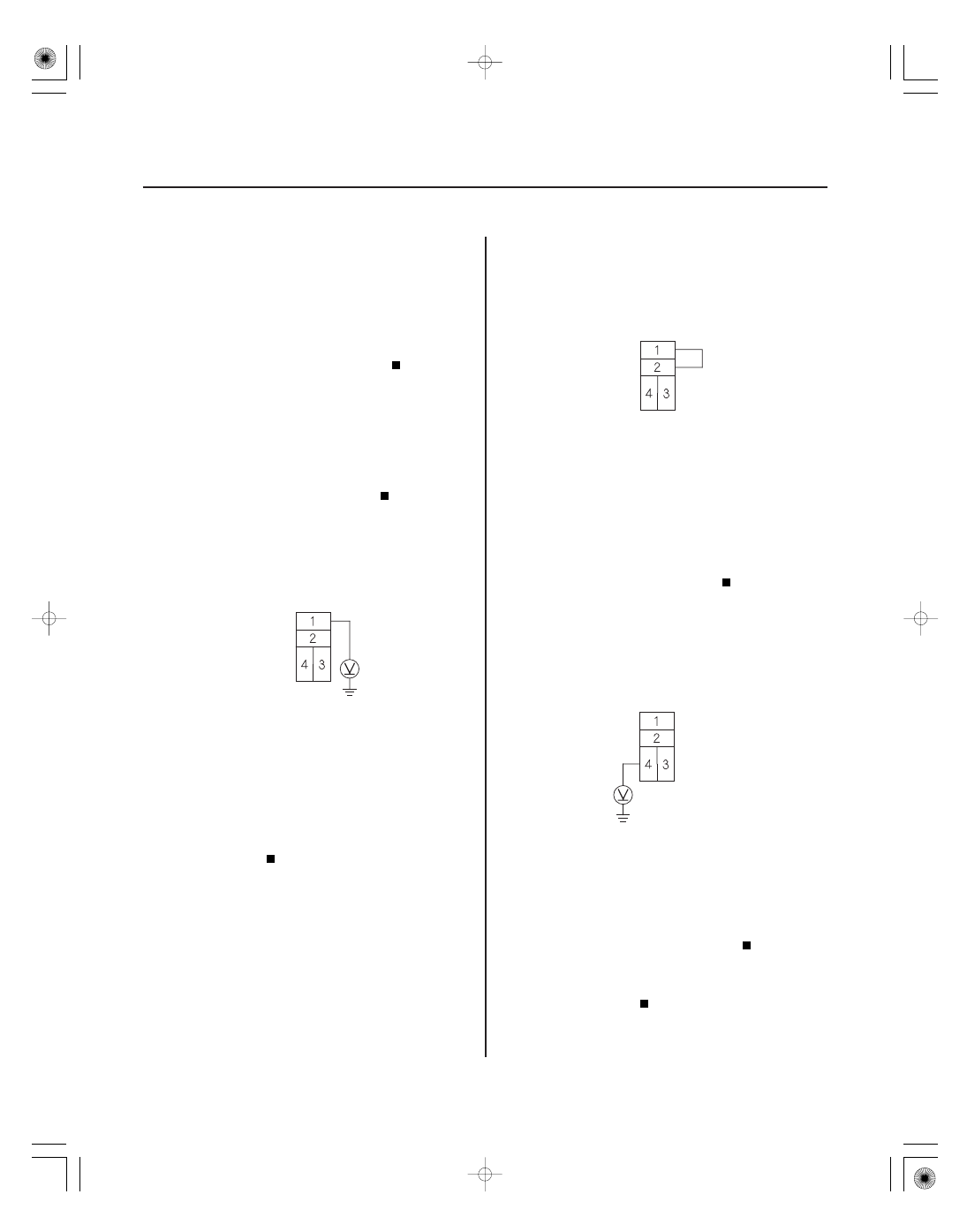
RADIATOR FAN RELAY 4P SOCKET
RADIATOR FAN RELAY 4P SOCKET
JUMPER WIRE
RADIATOR FAN RELAY 4P SOCKET
1. Check the No. 19 (30 A) fuse in the under-hood
fuse/relay box, and the No. 23 (7.5 A) fuse in the
under-dash fuse/relay box.
Go to step 2.
Replace the fuse(s) and recheck.
2. Remove the radiator fan relay from the auxiliary
under-hood relay box and test it (see page 22-75).
Go to step 3.
Replace the radiator fan relay.
3. Measure the voltage between the radiator fan relay
4P socket terminal No. 1 and the body ground.
Go to step 4.
Repair open in the wire between radiator fan
relay 4P socket terminal No. 1 and the under-hood
fuse/relay box.
4. Connect radiator fan relay 4P socket terminals
No. 1 and No. 2 with a jumper wire.
Go to step 5.
Repair open in the wire between the radiator
fan relay 4P socket terminal No. 2 and radiator fan
motor 2P connector terminal No. 2.
5. Turn the ignition switch ON (II).
6. Measure voltage between radiator fan relay 4P
socket terminal No. 4 and the body ground.
Repair open in the wire between the radiator
fan relay 4P socket terminal No. 3 and the
powertrain control module (PCM) (A5).
Repair open in the wire between the radiator
fan relay 4P socket terminal No. 4 and the under-
dash fuse/relay box.
Terminal side of female terminals
Terminal side of female terminals
Terminal side of female terminals
Ar e the f uses OK ?
Is the r elay OK ?
Is ther e batter y voltage?
Does the r adiator f an r un at high speed?
Is ther e batter y voltage?