Honda Odyssey 2004. Manual - part 407
−
−
−
−
14
*13
YES
NO
YES
NO
21-104
Climate Control
DTC Troubleshooting (cont’d)
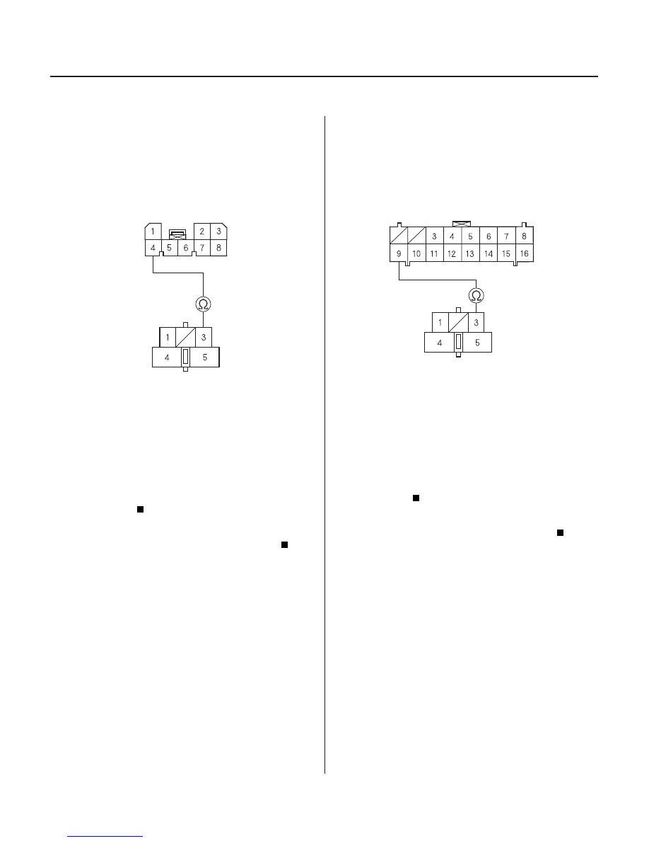
CLIMATE CONTROL UNIT CONNECTOR A (8P)
BLU/ORN
BLU/ORN
BLOWER MOTOR HIGH RELAY
5P CONNECTOR
CLIMATE CONTROL UNIT CONNECTOR A (16P)
BLOWER MOTOR HIGH RELAY 5P CONNECTOR
BLU/ORN
BLU/ORN
34. Disconnect climate control unit connector A (8P).
35. Check for continuity between the No. 4 terminal of
climate control unit connector A (8P) and the No. 3
terminal of the blower motor high relay 5P
connector.
Check for loose wires or poor connections at
climate control unit connector A (8P) and at the
blower motor high relay 5P connector. If the
connections are good, substitute a known-good
climate control unit, and recheck. If the symptom/
indication goes away, replace the original climate
control unit.
Repair open in the wire between the climate
control unit and the blower motor high relay.
36. Disconnect climate control unit connector A (16P).
37. Check for continuity between the No. 9 terminal of
climate control unit connector A (16P) and the No. 3
terminal of the blower motor high relay 5P
connector.
Check for loose wires or poor connections at
climate control unit connector A (16P) and at the
blower motor high relay 5P connector. If the
connections are good, substitute a known-good
climate control unit, and recheck. If the symptom/
indication goes away, replace the original climate
control unit.
Repair open in the wire between the climate
control unit and the blower motor high relay.
Wire side of female terminals
Wire side of female terminals
Wire side of female terminals
Wire side of female terminals
Is ther e continuity?
Is ther e continuity?
03/07/29 10:13:28 61S0X050_210_0105