Honda Odyssey 2004. Manual - part 406
−
−
−
−
−
−
−
−
*02
09
*03
YES
NO
YES
NO
YES
NO
YES
NO
21-100
Climate Control
DTC Troubleshooting (cont’d)
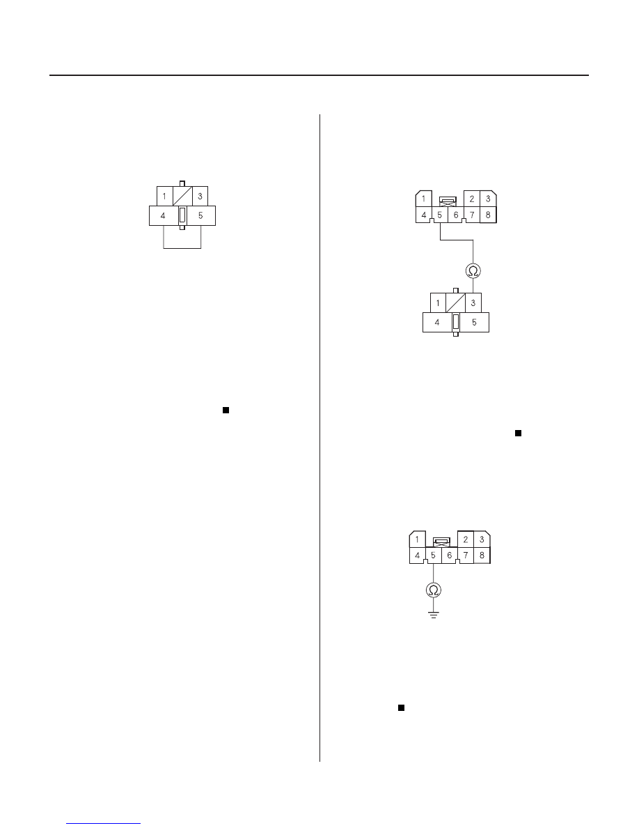
POWER TRANSISTOR 5P CONNECTOR
BLK
BLU/RED
JUMPER WIRE
CLIMATE CONTROL UNIT CONNECTOR A (8P)
ORN/BLK
ORN/BLK
POWER TRANSISTOR 5P CONNECTOR
CLIMATE CONTROL UNIT CONNECTOR A (8P)
ORN/BLK
4. Connect the No. 4 and No. 5 terminals of the power
transistor 5P connector with a jumper wire.
5. Turn the ignition switch ON (II).
Go to step 6.
Repair open in the wire between the power
transistor and the blower motor.
6. Turn the ignition switch OFF.
7. Disconnect the jumper wire.
Go to step 13.
Go to step 8.
8. Disconnect climate control unit connector A (8P).
9. Check for continuity between the No. 5 terminal of
climate control unit connector A (8P) and the No. 3
terminal of the power transistor 5P connector.
Go to step 10.
Repair open in the wire between the climate
control unit and the power transistor.
10. Check for continuity between the No. 5 terminal of
climate control unit connector A (8P) and body
ground.
Repair short to body ground in the wire
between the climate control unit and the power
transistor.
Go to step 11.
Wire side of female terminals
Wire side of female terminals
Wire side of female terminals
Wire side of female terminals
Does the blower motor r un at high speed?
Does the vehicle have a Navigation System?
Is ther e continuity?
Is ther e continuity?
03/07/29 10:13:25 61S0X050_210_0101