Honda Odyssey 2004. Manual - part 292


  Index      Honda     Honda Odyssey 2004 - service repair manual 2004 year


Search            


Content   ..  290  291  292  293   ..


Honda Odyssey 2004. Manual - part 292


±

*03

01

02

S0X4A00B20200065201MAAT00

Turning Angle Inspection

Turning angle:
Inward wheel:

41° 46’

Outward wheel: 33° 28’ (Reference)

Front/Rear:

Standard: 0

0.05 mm (0

0.002 in.)

Front:

Rear:

18-8

18-8

Front and Rear Suspension

Wheel Alignment (cont’d)

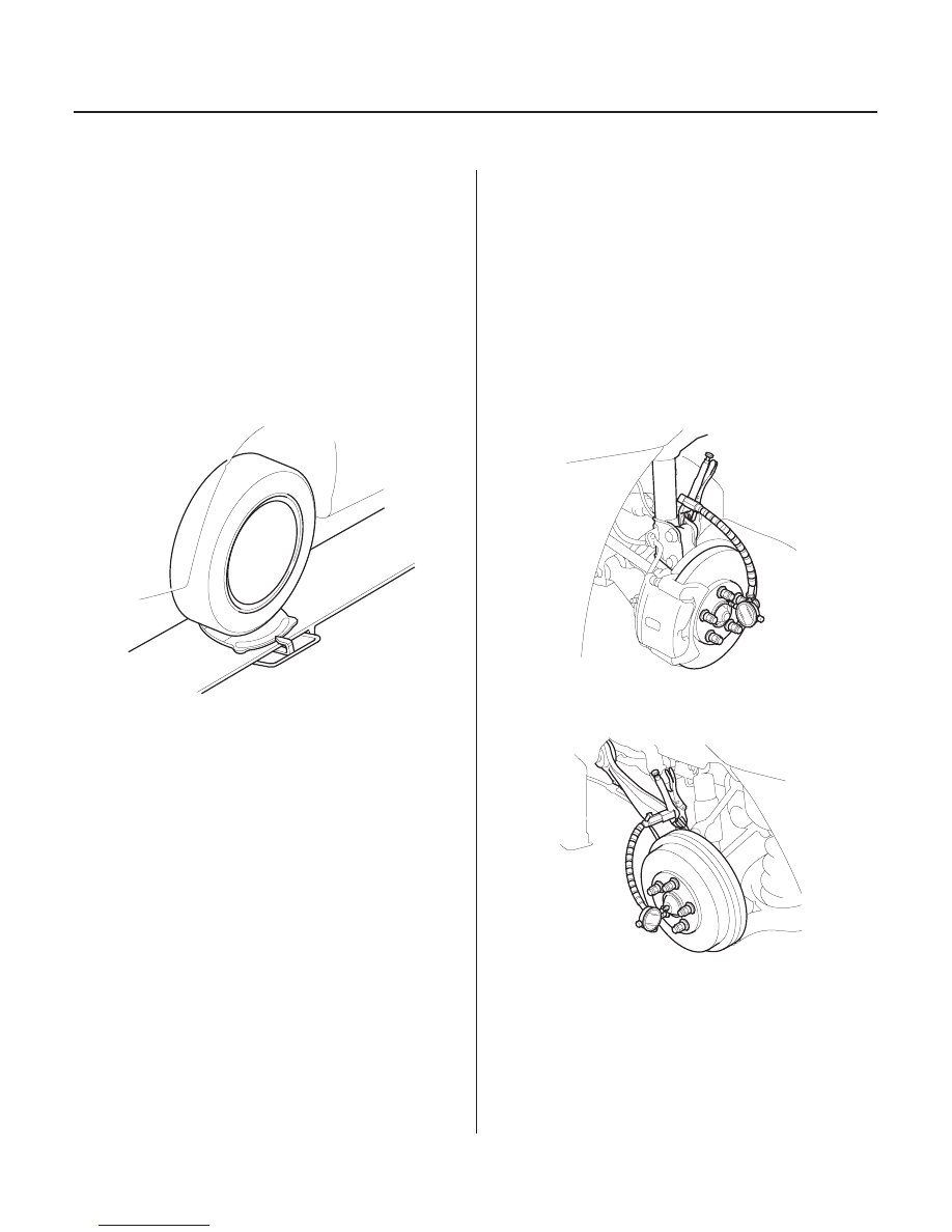
Wheel Bearing End Play Inspection

Use commercially-available computerized four wheel
alignment equipment to measure wheel alignment
(caster, camber, toe, and turning angle). Follow the
equipment manufacturer’s instructions.

1. Turn the wheel right and left while applying the

brake, and measure the turning angle of both
wheels.

2. If the turning angle is not within the specifications,

check for bent or damaged suspension
components.

1. Raise the vehicle, and support it with safety stands

in the proper locations (see page 1-15).

2. Remove the wheels, then reinstall the wheel nuts.

3. Attach the dial gauge. On the front, place the dial

gauge against the hub flange. On the rear, place the
dial gauge against the center of the hub cap.

4. Measure the bearing end play by moving the disc

or drum inward or outward.

5. If the bearing end play measurement is more than

the standard, replace the wheel bearing.

03/07/29 09:51:05 61S0X050_180_0008

*01

*02

S0X4A00B54100000000MAAT00

Front and Rear Wheel Axial Runout:

Standard:

Steel Wheel:

0

1.0 mm (0

0.04 in.)

Aluminum Wheel: 0

0.7 mm (0

0.03 in.)

Service Limit:

2.0 mm (0.08 in.)

Front and Rear Wheel Radial Runout:

Standard:

Steel Wheel:

0

1.0 mm (0

0.04 in.)

Aluminum Wheel: 0

0.7 mm (0

0.03 in.)

Service Limit:

1.5 mm (0.06 in.)

18-9

Wheel Runout Inspection

1. Raise the vehicle, and support it with safety stands

in the proper locations (see page 1-15).

2. Check for bent or deformed wheels.

3. Set up the dial gauge as shown, and measure axial

runout by turning the wheel.

4. Readjust the dial gauge to the position shown, and

measure radial runout.

5. If the wheel runout is more than the service limit,

replace the wheel.

03/07/29 09:51:06 61S0X050_180_0009

*01

*02

*03

*04

S0X4A00B20200014201KAAT00

Special Tools Required

18-10

Front and Rear Suspension

Ball Joint Removal

07AAF-SDAA100

A

A

B

07MAC-SL00200

07AAF-SDAA100

A

B

C

• Ball joint thread protector, 12 mm 07AAF-SDAA100
• Ball joint remover, 28 mm 07MAC-SL00200

1. Install the special tool nut onto the threads of the

ball joint (A). To prevent damage to the threaded
end of the ball joint.

2. Apply grease (A) to the special tool on the areas

shown. This will ease installation of the tool and
prevent damage to the pressure bolt (B) threads.

3. Install the special tool as shown. Insert the jaws

carefully, making sure you do not damage the ball
joint boot. Adjust the jaw spacing by turning the
pressure bolt.

4. Once the special tool is in place, turn the adjusting

bolt (A) as necessary to make the jaws parallel.
Then hand-tighten the pressure bolt (B), and
recheck the jaws to make sure they are still parallel.

5. After making the adjustment to the adjusting bolt,

make sure the head of the adjusting bolt is in this
position to the allow the jaw (C) to pivot.

6. With a wrench, tighten the pressure bolt until the

ball joint shaft pops loose from the steering
suspension arm. If necessary, apply penetrating
type lubricant to loosen the ball joint.

7. Remove the tool, then remove the ball joint thread

protector from the end of the ball joint, and pull the
ball joint out of the steering/suspension arm.
Inspect the ball joint boot, and replace it if
damaged.

03/07/29 09:51:07 61S0X050_180_0010

*01

S0X4A00B20200036401KBAT00

Exploded View

18-11

Front Suspension

Knuckle/Hub Replacement

WHEEL BEARING

SNAP RING

SCREW-WASHER
6 x 14 mm
9.8 N·m (1.0 kgf·m, 7.2 lbf·ft)

6 mm BRAKE DISC RETAINING SCREW
9.8 N·m (1.0 kgf·m, 7.2 lbf·ft)

FRONT HUB

BRAKE DISC

WHEEL NUT
12 x 1.5 mm
108 N·m
(11.0 kgf·m,
79.6 lbf·ft)

SPINDLE NUT
24 x 1.5 mm
245 N·m
(25.0 kgf·m, 181 lbf·ft)

SPLASH GUARD

KNUCKLE

CENTER CAP

FLANGE NUT
16 x 1.5 mm
157 N·m (16.0 kgf·m, 116 lbf·ft)

DAMPER PINCH BOLT
16 x 1.5 mm

(cont’d)

Replace.

Check for damage and
cracks.

Check for wear and
rust.

Replace.

Apply a small amount of engine oil
to the seating surface.

03/07/29 09:51:07 61S0X050_180_0011


Content   ..  290  291  292  293   ..