Honda Odyssey 2004. Manual - part 291


  Index      Honda     Honda Odyssey 2004 - service repair manual 2004 year


Search            


Content   ..  289  290  291  292   ..


Honda Odyssey 2004. Manual - part 291


*01

*02

S0X4A00B44100000000DAAT00

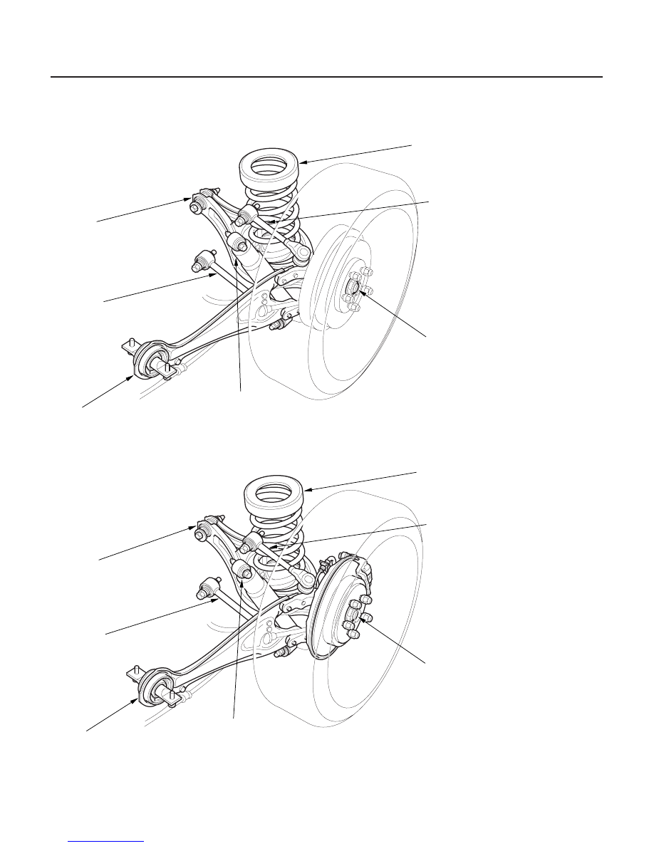
REAR DRUM BRAKE TYPE: ’99-01 models

REAR DISC BRAKE TYPE: ’02-04 models

18-4

Front and Rear Suspension

Component Location Index (cont’d)

REAR DAMPER

HUB/BEARING

TRAILING ARM

LOWER ARM A

LOWER ARM B

UPPER ARM

SPRING/
BUMP STOP

REAR DAMPER

HUB/BEARING

TRAILING ARM

LOWER ARM A

LOWER ARM B

UPPER ARM

SPRING/
BUMP STOP

Removal, page 18-30
Inspection, page 18-30
Installation, page 18-31

Replacement, page 18-22

Removal/Installation, page 18-29

Removal/Installation,

page 18-27

Removal,

page 18-28

Installation,

page 18-28

Removal/Installation, page 18-26

Removal, page 18-33
Installation, page 18-34

Removal, page 18-30
Inspection, page 18-30
Installation, page 18-31

Replacement, page 18-22

Removal/Installation, page 18-29

Removal/Installation,

page 18-27

Removal,

page 18-28

Installation,

page 18-28

Removal/Installation, page 18-26

Removal, page 18-33
Installation, page 18-34

03/07/29 09:51:03 61S0X050_180_0004

±

±

±

*01

S0X4A00B00000000000MBAT00

Front Caster Inspection

Front Camber Inspection

Caster angle: 2° 07’

Camber angle:
Front: 0° 00’

Rear:

0° 30’

45’

18-5

Wheel Alignment

For proper inspection/adjustment of the wheel
alignment, check and adjust the following before
checking the alignment:

• Check that the suspension is not modified.
• Check the tire size and tire pressure.
• Check the runout of the wheels and tires.
• Check the suspension ball joints. (Hold a wheel with

your hands, and move it up and down and right and
left to check for wobbling.)

Use commercially-available computerized four wheel
alignment equipment to measure wheel alignment
(caster, camber, toe, and turning angle). Follow the
equipment manufacturer’s instructions.

1. Check the caster angle.

2. If out of specification, check for bent or damaged

suspension components.

Use commercially-available computerized four wheel
alignment equipment to measure wheel alignment
(caster, camber, toe, and turning angle). Follow the
equipment manufacturer’s instructions.

1. Check the camber angle.

2. If out of specification, record the camber reading,

then adjust the camber.

(cont’d)

03/07/29 09:51:03 61S0X050_180_0005

±

±

*02

01

02

Front Camber Adjustment

Camber angle: 0° 00’

Maximum difference between the right and left
side: 1° 00’

18-6

Front and Rear Suspension

Wheel Alignment (cont’d)

Damper Pinch Bolt:

Adjusting Bolt:

P/N 90120-S0X-A00

A
16 x 1.5 mm
157 N·m
(16.0 kgf·m, 116 lbf·ft)

A

16 x 1.5 mm
157 N·m
(16.0 kgf·m,
116 lbf·ft)

The front camber can be adjusted by exchanging one or
both of the damper pinch bolts with a smaller diameter
adjusting bolt, P/N 90120-S0X-A00. The difference
between the adjusting bolt diameter and the pinch bolt
hole diameter allows for a small range of adjustment.

1. Measure the camber angle.

2. If the measurement is outside the specification, go

to step 3, and adjust the camber angle.

3. Raise the front of the vehicle, and support it with

safety stands in the proper locations
(see page 1-15). Remove the front wheels.

4. Loosen the flange nuts (A), and adjust the camber

by moving the bottom of the damper within the
range of the damper pinch bolt free play. Tighten
the flange nuts to the specified torque.

5. Reinstall the front wheels. Lower the front of the

vehicle to the ground, and bounce the front of the
vehicle several times to stabilize the suspension.

6. Measure the camber angle.

• If the measurement is within specification,

measure the toe-in.

• If the measurement is not within specification, go

to step 7.

7. Raise the front of the vehicle, and support it with

safety stands in the proper locations
(see page 1-15). Remove the front wheels.

8. Replace the damper pinch bolts with the adjusting

bolts (A), and adjust the camber angle.

NOTE: The camber angle can be adjusted up to

30’ (center of tolerance) by replacing one damper

pinch bolt with the adjusting bolt. The camber
angle can be adjusted up to 1° 00’ by replacing both
damper pinch bolts with the adjusting bolts.

9. Tighten the flange nuts to the specified torque

values.

10. Install the front wheels, and torque the wheel nuts

to 108 N·m (11.0 kgf·m, 79.6 lbf·ft).

11. Lower the vehicle to the ground, and bounce the

front of the vehicle several times to stabilize the
suspension.

12. Measure the camber angle. If the camber angle is

not within specification, repeat steps 8 through 12
to readjust the camber angle. If the camber
measurement is correct, measure toe-in, and adjust
it if necessary.

03/07/29 09:51:04 61S0X050_180_0006

±

±

±

±

*04

*05

Front Toe Inspection/Adjustment

Rear Toe Inspection/Adjustment

Front toe: 0

2 mm (0

1/16 in.)

Rear toe: 0

2 mm (0

1/16 in.)

18-7

B

A
14 x 1.5 mm
44 N·m
(4.5 kgf·m,
33 lbf·ft)

A

C
12 x 1.25 mm
83 N·m
(8.5 kgf·m, 61 lbf·ft)

B

Use commercially-available computerized four wheel
alignment equipment to measure wheel alignment
(caster, camber, toe, and turning angle). Follow the
equipment manufacturer’s instructions.

1. Check the tire pressure.

2. Center the steering wheel spokes.

3. Check the toe with the wheels pointed straight

ahead.

• If adjustment is required, go to step 4.
• If no adjustment is required, remove the

alignment equipment.

4. Loosen the tie-rod locknuts (A), and turn both

tie-rods (B) in the same direction until the front
wheels are pointing straight ahead.

5. Turn both tie-rods equally until the toe reading on

the turning radius gauge is correct.

6. After adjusting, tighten the tie-rod locknuts.

Reposition the tie-rod boot if it is twisted or
displaced.

Use commercially-available computerized four wheel
alignment equipment to measure wheel alignment
(caster, camber, toe, and turning angle). Follow the
equipment manufacturer’s instructions.

1. Release the parking brake to avoid an incorrect

measurement.

2. Check the toe.

• If adjustment is required, go to step 3.
• If no adjustment is required, remove the

alignment equipment.

3. Hold the adjusting bolt (A) on the rear lower arm B,

and loosen the self-locking nut (C).

4. Adjust the rear toe by turning the adjusting bolt

until the toe is correct.

5. Install the self-locking nut, and tighten it while

holding the adjusting bolt.

(cont’d)

03/07/29 09:51:05 61S0X050_180_0007


Content   ..  289  290  291  292   ..