Great Wall Hover. Manual - part 56


  Index      Great Wall     Great Wall Hover - service repair manual


Search            copyright infringement  


Content   ..  54  55  56  57   ..


Great Wall Hover. Manual - part 56


6

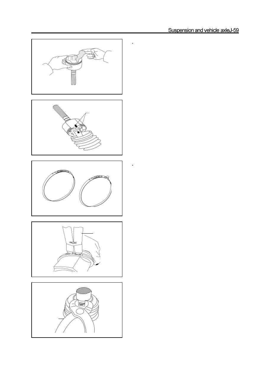
Install the inner trumpet connector on the front

     drive shaft

a. Fill the inner trumpet connector and inner jacket with the

   grease supplied with the jacket

(Recommend used grease is CAPLEX or KY1).  Amount About140g

       b. Align the assembly mark made during disassembly; covered

           with inner trumpet connector.

       c. Cover the inner jacket on the inner trumpet connector.

7

Use the inner and outer jacket clip pliers to

      clamp the inner and outer jacket.

a. Use the special non-ear clip pliers to lock the large clip of

inner jacket.

b. Use the nutcracker to lock the small clip of inner jacket.

Caution: Ensure the large and small connecting place of jacket

is in the corresponding groove of trumpet connector and shaft.

assembly mark

outer jacket clip

inner jacket clip

non-ear clip pliers

nutcracker

c.Use the special pneumatic pliers to lock the large and small clip of

   outer jacket.

d.Ensure the jacket of both sides does not be prolonged or shortened

   when the front drive shaft has the standard length.

Standard length: 400.5mm

If only need to replace the outer components of front drive

shaft assembly on car, it can remove the left and right steer-

ing knuckle of car, then disconnect the inner trumpet con-

nector of front drive shaft assembly, then take out the three-

pin section assembly and shaft from the inner trumpet con-

nector for replacement.

Installation of constant-speed drive shaft assem-
bly on front drive axle

1. Insert the hanger plank into the drive shaft, inserted

with oil seal; use the circlip pliers to install the inner

circlip.

Caution: It should replace the oil seal if damaged.

special tools

circlip pliers

support the lower end

 Use the special tools to knock bearing in slightly.

Caution: Support the lower end of the drive shaft assembly

when knock the bearing in. The lower end must not slide out.

3. Use the circlip pliers to install the outer circlip on

the front drive shaft assembly.

4. Repeat the previous method to install the hanger

plank, oil seal, circlip, bearing and circlip on another

end.

5. Insert the spline of connecting end of drive shaft

and reducer into the differential halfaxle gear spline

hole of electric clutch and reducer slowly.

6. Drip 1-2 drop of screw lock agent on the middle of

screw of connecting bolt of hanger plank andreducer.

7. Use the wrench to tighten the connecting bolt of

hanger plank and drive axle to specified torque.

specified torque : 90-110N

m

Caution: It should screw on all bolts before tighten

them, then tighten them in diagonal direction.

Check the hanger plank for levelness after tightened

the bolt to the specified torque. Remove the   hanger

plank and reinstall it if is not planished.

8. Install the vent tube connector assembly; connect

all ports to front drive axle.

(Refer to “Assembly of Front Reducer Assembly”)

special tools

support the lower end

Specified torque : 200-220N

m

Caution: Drip 1-2 drop of screw lock agent on the middle front

part of the lifting bolt

10 Use the bolt to connect the front drive axle flange

and drive shaft according to the mark mage before

disassembly and tighten it to the specified torque.

specified torque: 73-83N.m

11. Install the beam under the front drive axle.

Tighten the beam connecting bolt to the specified

torque.

specified torque: 73-83N.m


Content   ..  54  55  56  57   ..