Great Wall Hover. Manual - part 54


  Index      Great Wall     Great Wall Hover - service repair manual


Search            copyright infringement  


Content   ..  52  53  54  55   ..


Great Wall Hover. Manual - part 54


Stabilizer bar

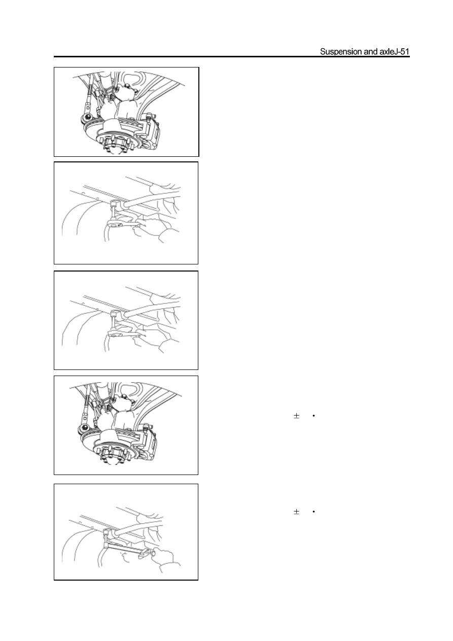
Disassembly of stabilizer bar

1. Disconnect the connecting bar which supports both

ends of the stabilizer bar form the stabilizer bar.

Use the inner hexagon spanner to fix the ball pin; remove the self-

locking nut.

2. Remove the bush and clip of stabilizer bar; remove

the stabilizer bar

Installation of stabilizer bar

1. Install the stabilizer bar on the carriage

Place the stabilizer bar in position; install the stabilizer bar bush and

clip on the carriage. Align the mark on the stabilizer bar to keep the

left and right gap of stabilizer bar are same. Then install the bolt

temporarily and pretighten it.

2. Connect the stabilizer bar to the connecting rod.

Install and tighten the new nut to the specified torque.

Tightening force: 63

5N

m

3. Tighten the clip position bolt to specified torque.

Tightening force: 23

2N

m

Constant-speed drive shaft assembly

Installation and disassembly drawing of front drive shaft assembly on front drive axle

hanger plank 

R

universal-joint bearing

front reducer and electric clutch assembly

Power plug of electric clutch

circlip

hanger plank 

L

constant-speed drive shaft

circlip

lower segment of vent tube of front drive axle

circlip

circlip

Pregummed component


m:    specified torque

universal-joint oil seal

universal-joint bearing

constant-speed drive shaft assembly

1. Place the car in the middle of repair platform or

   trench, support the front of the car steadily(support

on the carriage) then remove the left and right

front wheel.  (make the car in 2WD status before

the disassembly)

2. Remove the beam on the lower of front drive axle

    assembly.

3. Disconnect the connection of front drive axle

   flange and drive shaft and make the assembly

   mark

4. Drain the lubrication oil in reducer.

bolt

front hub cover

circlip

adjusting washer set

flange

disconnect three ports in this position

m:   specified torque

9. Use the wrench to screw off the bolt which fixes

    the lower segment assembly of front drive axle

    vent tube on the vent tube bracket.

10. Support the front drive axle by the jack; screw

      off the lifting bolt of hanger plank and carriage.

11. Remove the complete drive axle.

12. Screw off the connecting bolt of hanger plank and

      front drive axle assembly.

13. Pull out the left and right front drive shaft

     assembly with the oil seal, hanger plank and

     bearing.

se the circlip pliers to remove the outside circlip

      of bearing.

15. Use the special tools pull out the bearing.

16. Use the circlip pliers to remove the circlip on

      another side of bearing.

Caution: During the disassembly, support the lower end of

drive shaft and prevent the drive shaft from sliding out from

the inner jacket, meanwhile, it could not damage the inner

and outer jacket.

wrench

circlip pliers

support the lower end

hold

special tools

shim

support the lower end

supporting position


Content   ..  52  53  54  55   ..