Great Wall Hover. Manual - part 53


  Index      Great Wall     Great Wall Hover - service repair manual


Search            copyright infringement  


Content   ..  51  52  53  54   ..


Great Wall Hover. Manual - part 53


Upper suspension arm

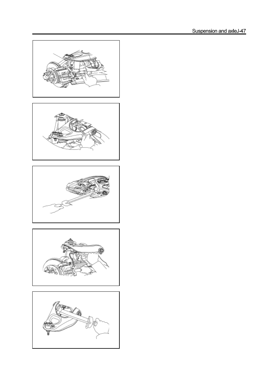
Disassembly of upper suspension arm

1. Disconnect the upper ball pin form the steering

knuckleRemove the split pin and nut; use the special

tools to disconnect the upper ball pin from the steering

knuckle.

2. Remove the brake oil pipe on the upper arm shaft

a. Use the open-end wrench to screw off the oil pipe tight nut.

b. Pull out the brake oil pipe and plug it by the rubber plug.

Remarks: There are two two-way valves for rear brake oil pipe

beside the right upper arm shaft ; when remove the right upper

suspension arm, it must remove four oil pipe tight nuts in the

place and plug it by the rubber plug to prevent the brake fluid

from overflowing.

3. Disconnect the brake hose form the brake caliper

Remove the hollow bolt and disconnect the brake hose

form the brake caliper

Remarks: Must not lose the copper gasket seal.

4. Disconnect the brake hose from the upper arm oil

pipe bracket.

Use the pliers to pull out the sheet steel spring clip and

disconnect the brake hose from the upper arm oil pipe

bracket.

5. Remove the upper suspension armRemove two bolts

and remove the upper suspension from the armcarriage.

Remarks: Keep the adjusting shim and don’t lose it. Record the

thickness of front and rear adjusting shim for convenience of

reinstalling them in the original position.

special tools

Replacement of upper arm bush

1. Remove the bush

a. Remove the bolt and washer.

b. Use the special tools to push out the bush.

c. Remove the upper arm shaft; remove another bush in same

procedure.

2. Install the bush

a. Use the special tools to press in the bush.

b. Install the upper arm shaft; use the special tools to press in

another bush.

3. Tighten the upper arm shaft to specified torque.

a. Coat the screw of both ends of upper arm shaft with the

screw lock sealant; install the washer and nut.

Remarks: Adjust the position of upper lower; make the

installation plane of ball pin is vertical to the installation

plane of upper arm shaft.

special

special

special

b. Tighten the upper arm shaft nut to specified torque.

 Tightening force: 210

10N

m

Installation of upper suspension arm

1. Install the upper suspension arm on the carriage

a. Install the upper suspension arm and camber adjusting shim.

b. Tighten all bolts to the specified torque.

 Tightening force: 200

10N

m

Remarks: Install the shim with same quantity and thickness to the

original position.

2. Connect the brake oil pipe of upper arm shaft Tighten

    the oil pipe compression nut to specified torque.

Tightening force: 15-17N

m

Remarks: It should tighten four connectors of two two-way valves

to the specified torque if disassemble the right upper arm.

3. Connect the brake hose to the upper arm oil pipe

    bracket

a. Thread the brake hose through the hole on upper arm oil pipe

 bracket.

 b.  Insert the sheet steel spring clip by the hammer to fix the brake

 hose.

4. Connect the upper ball pin to the steering knuckle.

a. Tighten the slotted nut according to the specified torque.

  Tightening force: 145

15N

m

 b.  Install the new split pin.

Remarks: It should align the notch of nut with the pinhole when

install the split pin; the nut can be tightened but not loosed during

the alignment.

5. Connect the brake hose to the brake caliper.

Install the copper gasket seal and tighten the hollow bolt to the

specified torque.

Tightening force: 50±5N·m

6. Discharge the air in front brake system

(Refer to relevant chapter)

Remarks: It must discharge the air in the rear brake system

if disassembly the right upper arm.

7. Check the brake fluid for leakage

8. Tighten the upper arm front shaft nut to the

specified torque

a. Install the wheel, remove the bracket and bounce the vehicle for

    several times to make the vibration damper enters into the stable

    status.

b.Align the assembly mark and tighten the nut to the specified

    torque.

Tightening force: 240±20N·m

9. Check the wheel alignment parameter

(Refer to 4-Wheel Alignment)


Content   ..  51  52  53  54   ..