Great Wall Hover. Manual - part 51


  Index      Great Wall     Great Wall Hover - service repair manual


Search            copyright infringement  


Content   ..  49  50  51  52   ..


Great Wall Hover. Manual - part 51


Ball pin

Check of ball pin

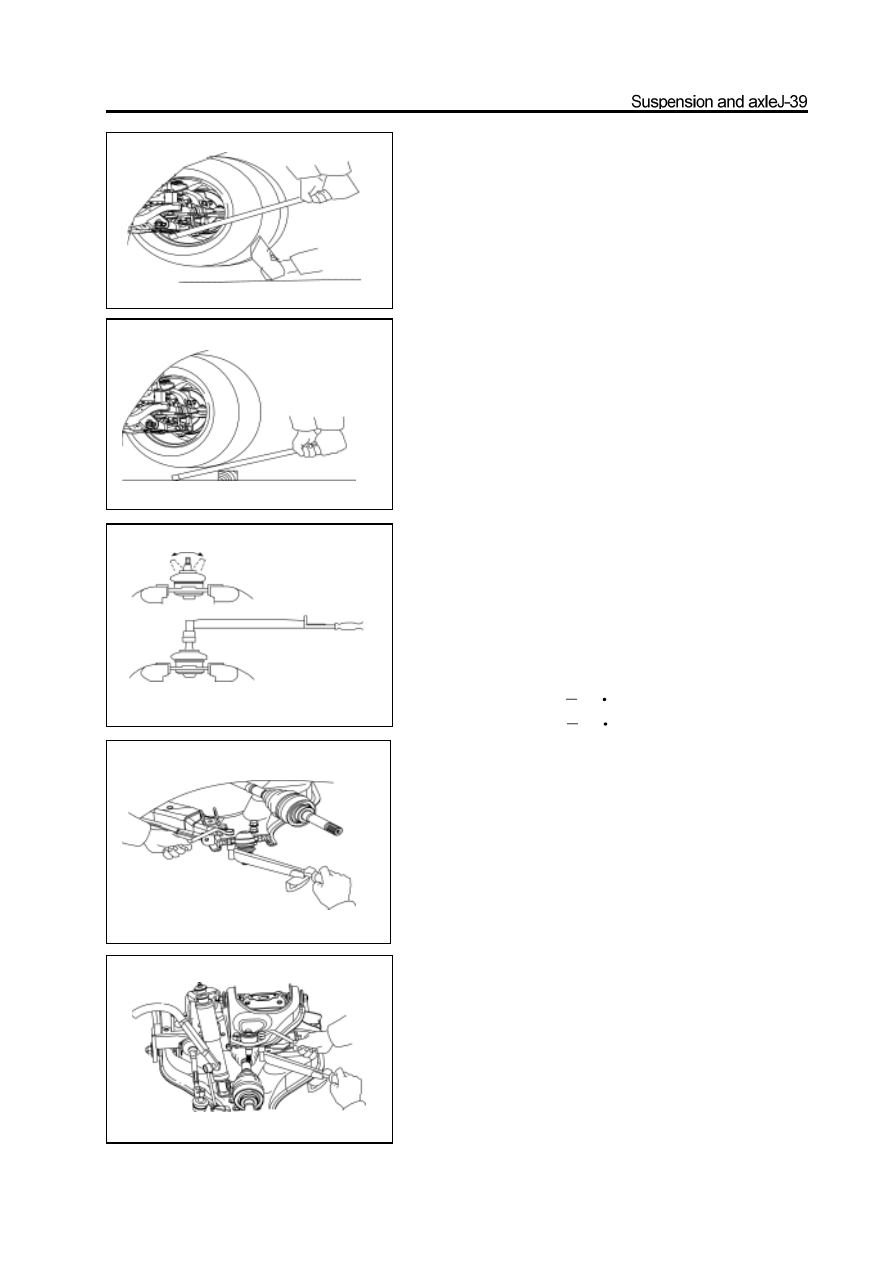
1. Check the lower ball pin for loose

a.   Raise the front of the car by jack and support it by the frame.

b. Ensure the front wheel is in straight advancing position and step

down the brake pedal.

c. Move the arm upwardly and downwardly; check

the clearance of lower ball pin.

 Max. vertical clearance: 0mm

2.  Check the upper ball pin for loose move the wheel

      upwardly and downwardly and check the gap of

      upper ball pin.

Max. vertical clearance: 0mm

3. Check the rotation of ball pin

a. Remove the ball pin.

b.   Shown as figure, shake the ball pin stud forwardly and backwardly

for several times before install the nut

c. Rotate the nut continuously by torsion meter and 2-4s for a

cycle; record the readout of torsion meter in the fifth cycle.

 Tightening torque (for rotary):

 Lower ball pin   0.1

4N

m

 Upper ball pin   0.1

4N

m

Disassembly of ball pin

1. Remove the steering knuckle and front hub assembly

(Refer to section “Front Hub and Steering Knuckle”)

2. Remove the lower ball pin form the lower arm

3. Remove the upper ball pin from the upper arm

Installation of ball pin

1. Install the upper ball pin on the upper arm

Tightening force: 78

5N

m

2. Install the lower ball pin on the lower arm

Tightening force: 140

10N

m

3. Install the steering knuckle and front hub assembly

(Refer to section “Front Hub and Steering Knuckle”)

Torsion bar spring

Disassembly of torsion bar spring

1. Make the assembly mark on the torsion bar spring,

    torsion base and adjusting arm

2. Measure the length A of extension section of bolt

    according to the length shown in figure.

Remarks: The measuring value is for reference when adjust the

ground clearance of chassis.

3. Loose the adjusting bolt until the torsion bar spring

    has not the tension.

4. Remove the fixed arm and torsion bar spring

Installation of torsion bar spring

Remarks: There are the L and R indication marks, which must not

be exchanged on the rear end of the torsion bar spring. Mark L

means the left while R for right

1. For reused torsion bar spring

a. Cost the spline of torsion bar spring with grease thin.

b. Align the assembly mark and install the torsion bar spring on the

torsion bar.

 c.   Align the assembly mark and install the adjusting arm on the

  torsion bar spring.

d. Tighten the adjusting bolt and make the extension length of the

bolt equal to the value before disassembly.

2. For new torsion bar spring

a.  Remove the wheel.

b.  Coat the spline of torsion bar spring with thin grease.

 c.  Install the torsion bar spring on the torsion bar  base.

d. Lower the lower arm to the lower limitation position; install

the adjusting arm in the torsion bar spring with the angle that

the adjusting bolt just can be screwed on the upper adjusting

block.

Remarks: It can repeat for several times until proper  when

adjust the angle.

e.  Tighten the adjusting bolt to the specified torque.

Nut tightening limitation: A is about 20-35mm; if A>35mm,

then it is adjusted through height of adjusting arm.

f. Install the wheel; remove the bracket; bounce the vehicle for

several times to make the suspension enters into the stable

status.

g.   Rotate the adjusting bolt and adjust the ground clearance of

 chassis (Refer to 4-Wheel Alignment).


Content   ..  49  50  51  52   ..