Great Wall Hover. Manual - part 50


  Index      Great Wall     Great Wall Hover - service repair manual


Search            copyright infringement  


Content   ..  48  49  50  51   ..


Great Wall Hover. Manual - part 50


e. Use the jack to raise the lower arm; remove the steering knuckle.

Check and replacement of steering knuckle

1. Check of steering knuckle

Use the dye penetrant to check the steering knuckle for crack.

It should replace the steering knuckle if has crack.

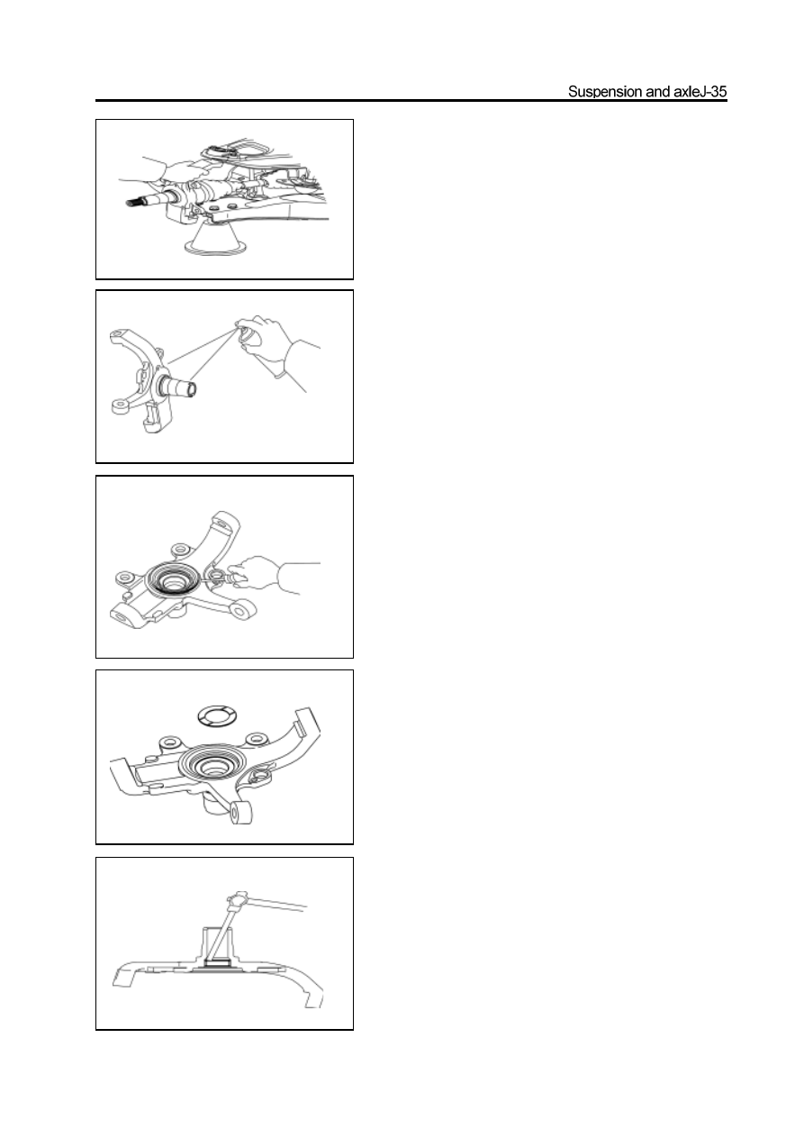
2. Remove the steering knuckle oil seal

Use the screwdriver to pry out the oil seal from the steering knuckle.

3. Take out the thrust plate

4. Remove the needle bearing

Use the copper bar and hand hammer to knock out the needle

bearing.

5. Installation of needle bearing

Use the special tools and hand hammer to knock in the new

needle bearing slightly.

Remarks: The thicker end of needle bearing should be

upwardly when knock in. with thicker end.

chamfer

steering

knuckle

6. Installation of thrust plate

Coat the installation position of thrust plate of steering knuckle

with the HP-R grease; place the thrust plate with the surface

with chamfer facing the steering knuckle.

Remarks: It must measure the thickness of the thrust plate

before the installation; it should install the new thrust plate if

the thickness is less than 1.5mm. The nominal thickness of

the new thrust plate is 2mm.

7. Installation of steering knuckle oil seal

Use the special tools and hand hammer to knock in the new

steering knuckle oil seal slightly.

Installation of steering knuckle

1. Install the steering knuckle

a. Coat the drive shaft and inner of drive shaft dustproof cove

with the lithium base grease.

b. Insert the drive shaft into the steering knuckle, meanwhile

connect the lower ball pin to the steering knuckle and install the

slotted nut temporarily.

special

tools

special

tools

c. Press down the upper arm and connect the upper ball pin to the

steering knuckle. Install and tighten the nut to the specified

torque.

Tightening force: 145

15N

m

d. Install the new split pin.

Remarks: It should align the notch of nut with the pinhole when

install the split pin; the nut can be tightened but not

loosedduringthealignment.

e. Install and tighten the lower ball pin nut to specified torque.

Tightening force: 230

20N

m

f. Install the new split pin.

Remarks: It should align the notch of nut with the pinhole when

install the split pin; the nut can be tightened but not

loosedduringthealignment.

2. Connect the stabilizer bar to the lower arm

Support the lower arm by jack; use the inner hexagon spanner to fix

the ball pin and tighten the self-locking nut to specified torque.

Tightening force: 63

5N

m

3. Connect the steering cross rod to the steering

    knuckle arm

a. Tighten the slotted nut according to the specified torque.

Tightening force: 170

15N

m

b. Install the new split pin.

Remarks: It should align the notch of nut with the pinhole when

install the split pin; the nut can be tightened but not

loosedduringthealignment.

4. Install the brake cover

Tightening force: 23

3N

m

5. Install the front hub and disc brake

(Refer to section “Front Hub”)

clip

Front suspension (4WD)

m:    specified torque

Used component which can not be used any more.

Pregummed component

rubber sleeve

front shaft of

lower arm

disk shim

fill block

shim

fill block

disk shim

shock Absorber

front hub and steering

knuckle assembly

split pin

lower ball pin

adjusting bolt

lower adjusting block

fixed arm

upper
adjusting
block

l ower arm

rear shaft of lower arm

Torsion base

torsion
bar

lower arm long bush

split pin

upper ball pin

upper arm

shim

upper arm bush

upper arm shaft

upper arm bush

shim

front stabilizer bar

flat shim

connecting rod of stabilizer bar

flat shim

lower arm short bush

eccentric shim


Content   ..  48  49  50  51   ..