Great Wall Hover. Manual - part 37


  Index      Great Wall     Great Wall Hover - service repair manual


Search            copyright infringement  


Content   ..  35  36  37  38   ..


Great Wall Hover. Manual - part 37


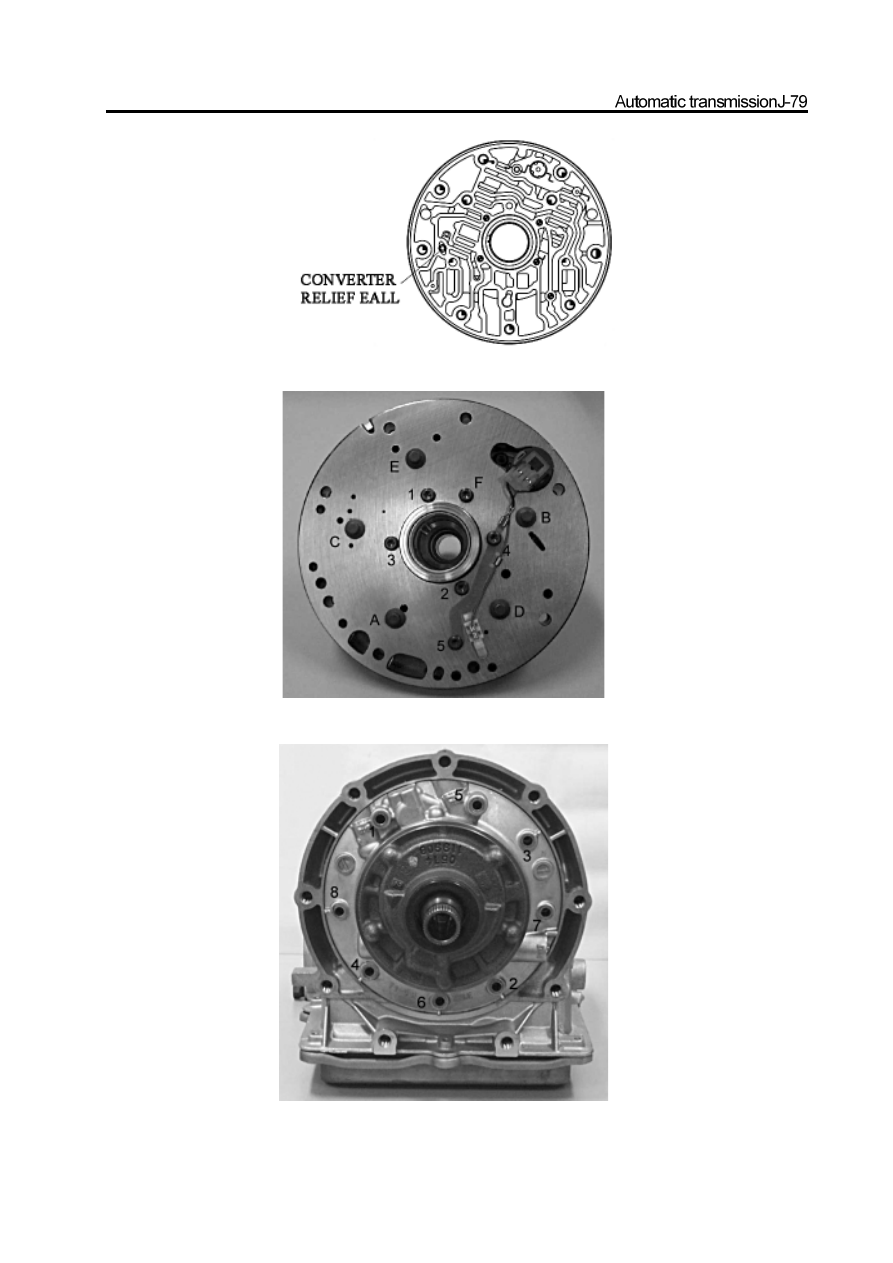
Figure 8.41  Position of test ball

Figure 8.42  Tighten the pump bolt in the sequence shown in figure

Figure 8.43  Connect the pump to the housing in the sequence shown in figure

14.   Valve

Caution:

a. Must not clean the solenoid valve pipe port by solvent.

b. Pay attention to the position of ball on upper of valve.

c. Pay attention to the position of 1-2 Gear and 3-4 Gear gear shift valve which may be exchanged.

d. Check the 4-3 Gear sequence valve and spring for position.

e. Check the 12mm ball on the lower of valve.

f. It should ensure install the correct pump housing  (HPPC). Please must not mix the 1

st

-Gearlow position ball spool

with the torque converter ball spool .

g. Check the rag of line pressure relief valve and pay attention to replace the iron shim.

h. The hole on the valve is used for fixation and safety and could not be extended.

i. When repair the transmission, it should ensure the solenoid 5 damp coil spring is not broken.

The installation procedure of valve is shown as follows:

a. Use the cleaning solvent (refer to 8.45, 8.46) to wash the upper and lower valve completely and dry it by air; check the valve

cavity, port and hole for damage or block.

b.   Install the cushioning baffle positioning bolt and clean all loose parts completely.

c. Check all valves for smooth sliding on its position.

d. Install the proper pump housing, spring and ball. Check the valve and rolling bolt.

e. Install the 1-2 Gear gear shift valve, plug and fixed bolt. Refer to Figure 8.48. Install the 3-4 Gear gear shift valve and fixed bolt.

Refer to Figure 8.49.

Install the 2-3 Gear gear shift valve and fixed bolt. Refer to Figure 8.50. Install the 4-3 sequence valve, spring, plug and fixed
disc.

Refer to Figure 8.51.

f. Install the brake belt action regulating valve (BAR) spring, piston and fixed bolt. Refer to Figure 8-52

g. Install the force and action regulation valve (CAR)spring, piston and fixed bolt. Refer to Figure 8-53

 Caution:  The aluminum valve is damaged easily.

h.   Install the solenoid pressure-supply valve, spring and fixed disc. Refer to Figure 8.54.

      i.    Install the solenoid valve 6 bolt , spring and fixed bolt.

Figure 8.45 Lower valve

Figure 8.46 Position of upper valve and detection ball

Figure 8.47 solenoid valve 5 and damper

Figure 8.48  1

2gear shift valve

Figure 8.49  3

4 gear shift valve

Figure 8.50   solenoid 2 and 2

3gear shift valve

Figure 8.51  4

3sequence valve

Figure 8.52  brake belt combination regulating valve and solenoid 4


Content   ..  35  36  37  38   ..