Great Wall Hover. Manual - part 35


  Index      Great Wall     Great Wall Hover - service repair manual


Search            copyright infringement  


Content   ..  33  34  35  36   ..


Great Wall Hover. Manual - part 35


v.    Install the thrust disc on the cylinder internal wheel axle. Refer to Figure 8.24and 8.19.

w.   Connect the C2 /clutch C4  wheel axle assembly in clutch C4 disc, install the clutch C2 disc. Install the C3 wheel axle and

         reinforce it by ring spring; ensure the ring spring is installed in the groove fixedly. Please refer to Figure 8.24.

10. Clutch C3 and reverse central gear system

The assembly procedure of clutch C3 and reverse central gear assembly  (refer to Figure 8.28) is shown as follows:

 Check the cleanness of hole on cylinder.

Caution:

It should take out the clutch clearance assembly before immerse the assembly into the automatic transmission fluid

(ATF).

s.     Use the gear selection plate to reach the correct specification. It should remove the clutch assembly and immerse the friction

disk in the automatic transmission fluid for 5 minutes at least before the installation if install the new friction disks. Lubricate

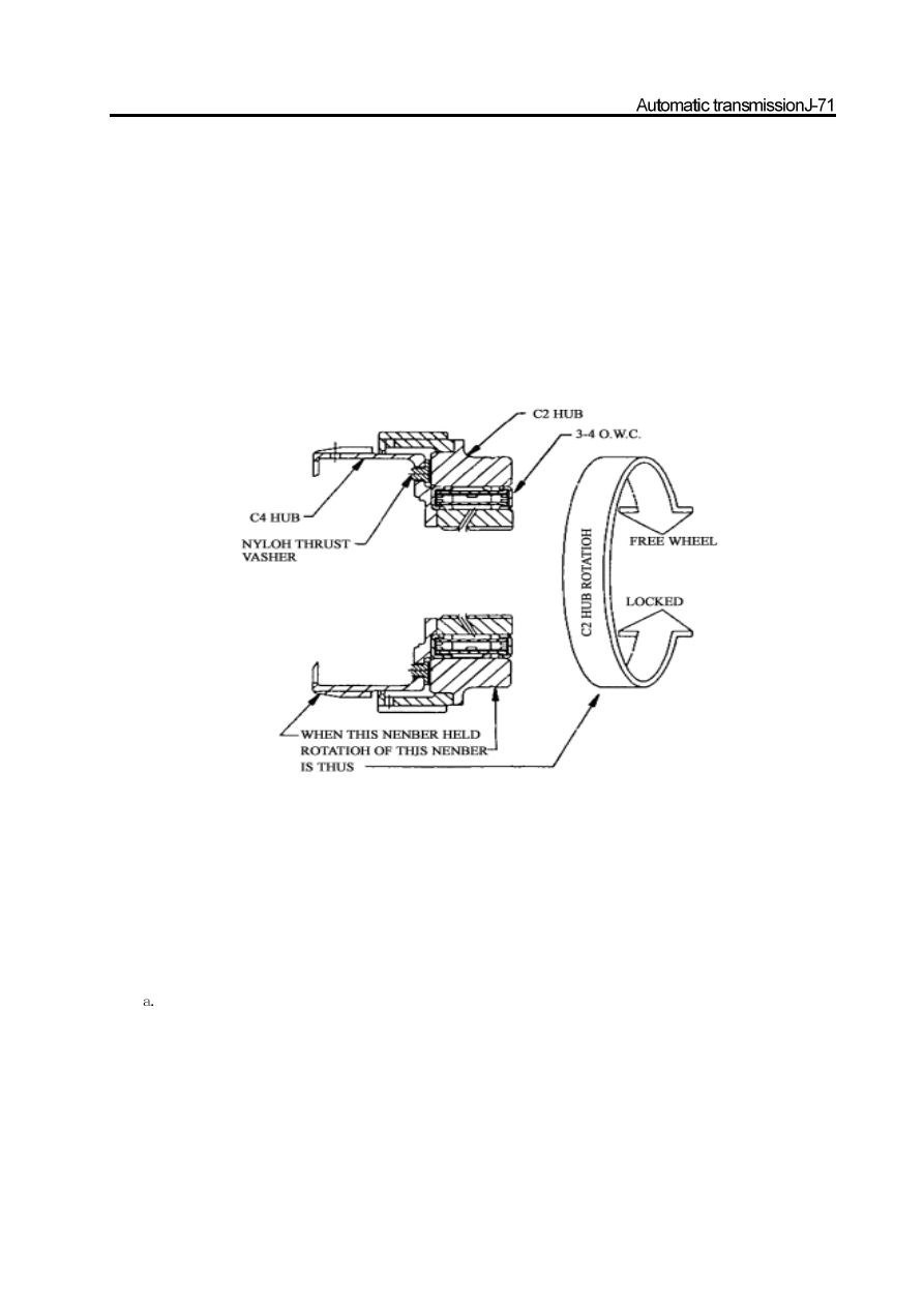
and install the 3-4 one-way clutch and install the sleeve on the C2 wheel axle. Adjust the handle rear and install the nylon thrust

washer on the C4 wheel axle. Refer to Figure 8.27.

t. Adjust and install the clutch C4 wheel axle on the clutch C2 and one-way clutch assembly. Check the rotary direction of clutch

C2 wheel axle, when keep the C4 wheel axle in static, C2 wheel axle should rotate in clockwise and is locked in anticlockwise.

Refer to Figure 8.27.

u.    Use the Vaseline to lubricate the N0.5 thrust bearing and install it on the C4 gear wheel axle ,separate the clutch C2 disc form

        the clutch cylinder.

Figure 8.27 C2 hub rotation

b. Check the damage of external diameter and central support diameter of C3 cylinder sleeve. Coat the sealing ring with the

automatic transmission fluid and install it on the C3 cylinder groove.

c. Check the condition of reverse central gear spline, notch and thrust surface; coat the O-ring with transmission liquid and install

it in the reverse sun gear groove. Use the Vaseline to lubricate the C3 washer and install it in the reverse sun gear.

d. Install the reverse central gear in the C3 cylinder; ensure the O-ring is compressed properly but not excess.

Caution:

The O-ring notch can not be bent.

e. Coat the C3 piston O-ring with the transmission liquid and install the small O-ring on the C3 piston inner ring; install the large

O-ring on the C3 piston external ring.

f. Check the piston drainage hole for cleanness and block material.

Caution:

Must not remove the O-ring without permission.

g. Install the C3 piston on the cylinder until the external diameter of piston enters into the inner diameter of cylinder.

h. Install the spring and spring retainer on the piston. Use the tools to press down the spring to install the ring spring better.

Ensure the ring spring is installed in the groove fixedly, then remove the tools.

i.

Install the C3 wave plate on the C3 piston surface; ensure the a hole on wave disc of C3 piston surface is not in line with the

piston hole.

j.

Install the clutch disk and other disc in the following sequence:

steel disc

friction disk

steel disc  (optional)

friction disk

steel disc  (optional)

friction disk

k. Adjust and install the pressure disc; make its counterbore is opposite with the clutch disk.

l. Install the ring spring.

Caution:

For the clutch assembly can endure the weight of 19.6N. so the clearance between the screw and top of preset disc should

be 1.20-1.45mm.

m. Use the tools to check the clearance of clutch C3, refer to Figure 8.29. The method is as follows (only use the weights):

 Place the weights on the pressure disc and measure the distance between the bottom of cylinder and top of pressure disc.

 Record the data.

 Remove the weights.

 Lift the weights plate and press down the ring spring; measure the distance between the bottom of cylinder and top of

pressure disc

 Record the data.

The clutch assembly clearance can be acquired by 1

st

 record minus 2nd record.

Figure 8.28  clutch C3  and reverse central gear

Figure 8.30  Forward-Gear central gear and C3clutch assembly

Caution:

It should take out the clutch assembly clearance before immerse the assembly into the transmission liquid.

n. It should remove the clutch and immerse the assembly into the transmission liquid for 5 miniatures at least before the

reassembly.

11. front sun gear and clutch C3  assembly

The installation procedure of front sun gear and clutch C3  assembly  (Refer to Figure 8.30) is shown as follows:

a. Install the N0.7 needle thrust bearing on the front sun gear ensure the thrust washer is between the bearing and central gear.

b. Use the Vaseline to lubricate the thrust plate and install it on the reverse sun gear. Refer to Figure 8.32.

c. Adjust and install the clutch C3 assembly on the front sun gear.

d. Use the Vaseline to lubricate the NO.6 needle thrust bearing and install it on the thrust disc. Ensure the wire connecting

plate on the bearing external diameter is proper for the hole on the thrust bearing. Refer to Figure 8.33.

e. Adjust and use the Vaseline to install the plastic thrust washer on the thrust disc.

f. Install the assembly on the reverse sun gear in the position opposite to the NO.6 thrust bearing.

g. Install the assembly on the other side.

12. Clutch C1 overspeed shaft and input shaft assembly

Caution:

     a. Ensure the correct installation of snap ring.

     b. Check the piston for crack.

     c. Must not mix the clutch piston out and back spring.

     d.  If the connector of clutch C1/ C2 is disconnected form the clutch C3, ensure the NO.6 bearing can not slide down

          from the bearing retainer.

The installation procedure of clutch C1 overspeed shaft and input shaft assembly is as follows:

a. Check the overspeed shaft groove for damage.

b. Coat the big and small sealing ring with the Vaseline and install it on the overspeed shaft. It can use few Vaseline to fix the

sealing ring on its correct position.

c. Install the clutch disk and other disc on the cylinder according to the following sequence:


steel plate

abrasion plate

steel plate

abrasion plate

steel plate

steel plate

steel plate  (optional)

friction disk

steel plate  (optional)

friction disk

Caution:

The clutch assembly can support the weight of 19.6N; the distance form the fixing point of input shaft to the friction disk
is 0.70

0.90mm.

Caution:

It should take out the clutch assembly before immerse the assembly in the transmission fluid.

     d. Use the tools to check the clutch assembly clearance. Refer to Figure 8.31. Use the proper selected disc plate to acquire the

correct required clearance.

Figure 8.31 clutch C1 assembly clearance

clutch C1

19.6N load

input shaft position

clutch clearance0.7-0.9mm0.7-0.9mm


Content   ..  33  34  35  36   ..