Great Wall Hover. Manual - part 11


  Index      Great Wall     Great Wall Hover - service repair manual


Search            copyright infringement  


Content   ..  9  10  11  12   ..


Great Wall Hover. Manual - part 11


b. Remove the lower cover plate assembly

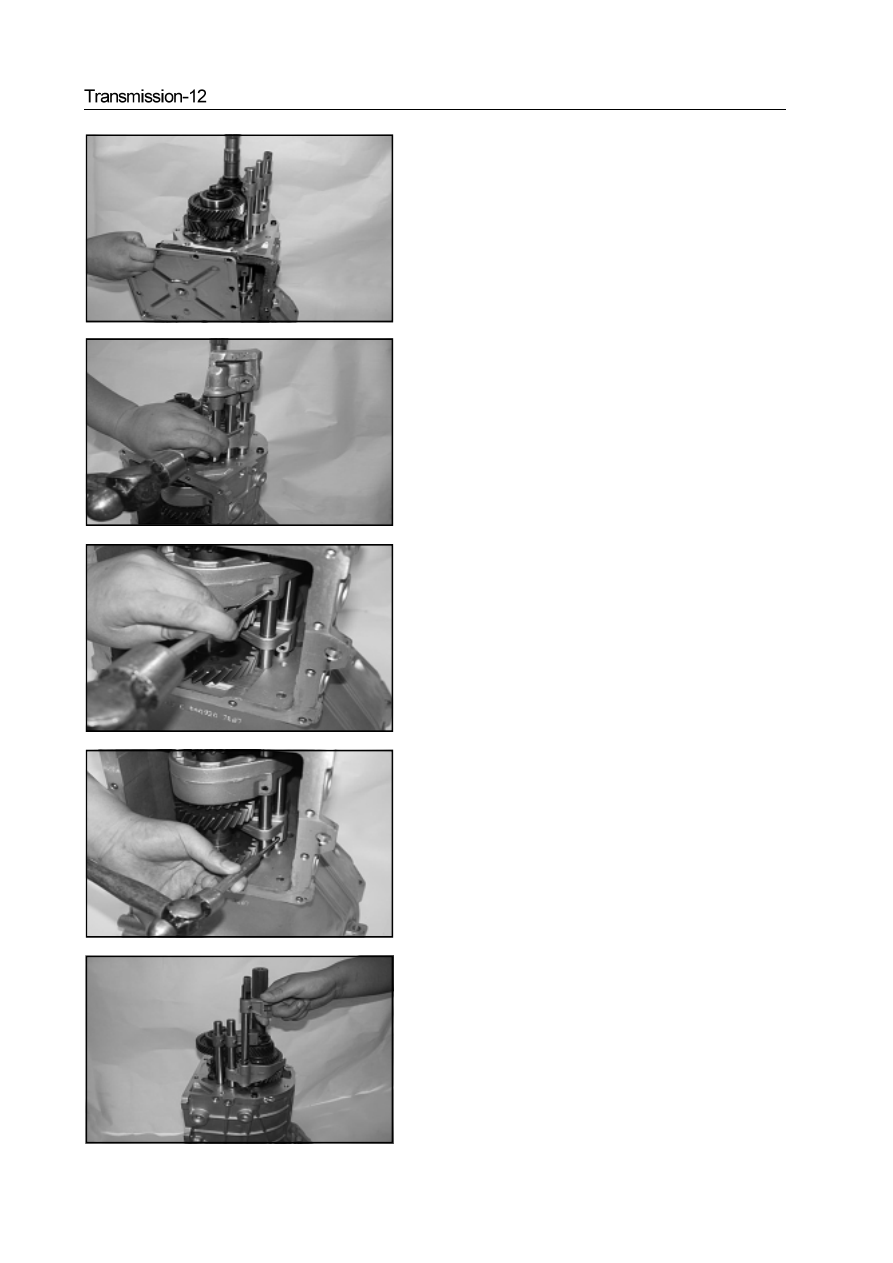
17. Remove the declutch shift shaft assembly

a. Use the punch to remove the reverse gear 5 shift fork elastic

cylindrical pin

b. Use the punch to remove the Gear 1/2 shift fork elastic cylindrical

pin

c. Use the punch to remove the Gear 3/4 shift fork cylinder pin.

d. Remove the reverse  gear 5 declutch shift shaft assembly

e. Remove the gear 3/4 declutch shift shaft assembly

f. Remove the reverse gear 5 shift fork

18. Remove the lock nut of intermediate shaft

Caution:  When install the lock nut of intermediate shaft , the

tightening torque is 160-190N·m

19.Remove the Gear 1/2 declutch shift shaft assembly, intermediate

shaft  rear ball bearing, 5th-Gear drive gear

20. Remove the Gear 1/2 shift fork

21.Use the special tools to remove the second shaft lock nut

Caution: When install the second shaft lock nut, the  tightening

torque is :   250-270N·m

22.Remove the thrust plate

23.Use the magnetic rod to remove the steel ball.

24.Remove the 5th-Gear driven gear assembly

Caution: When install the 5th-Gear driven gear assembly, it should

use the plug gage to test the 5th-Gear driven gear assembly axial

clearance, ensure the axial clearance is  within 0.170-0.284mm

25.Remove the 5th-Gear driven gear needle bearing

27. Use the pliers to remove the split pin on the reverse shaft lock

      nut.

28. Use the special tools to remove the reverse lock nut

Caution: when install the reverse lock nut, the tightening torque

is within 20-60N·m

29. Remove the thrust plate

30. Remove the 5th/reverse -Gear synchronizer assembly

a. Use the special tools to remove the 5th/reverse -Gear synchronizer

assembly

26. Remove the synchronizer gear ring

Caution: When install the synchronizer gear, it should use the

plug gage to test the synchronizer gear ring axial clearance, en-

sure the axial clearance is within 1.25-1.65mm


Content   ..  9  10  11  12   ..