Dodge Durango (HB). Manual - part 359


  Index      Dodge     Dodge Durango (HB) - service repair manual 2005 year


Search            


Content   ..  357  358  359  360   ..


Dodge Durango (HB). Manual - part 359


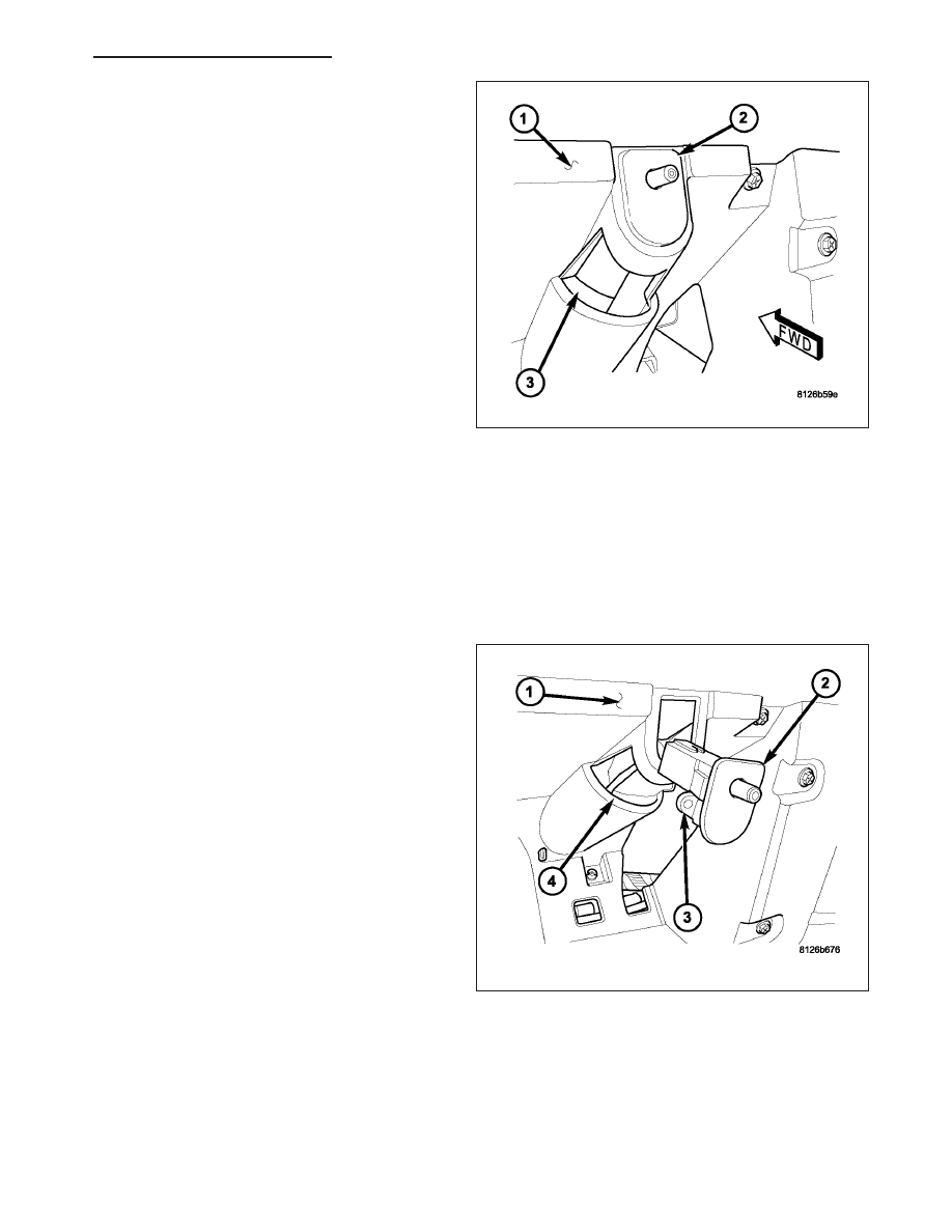
1. Reach through the window (3) in the instrument

panel glove box opening (1) to align the base of
the bulb with the bulb holder on the lower side of
the glove box lamp and switch unit (2).

2. Push the bulb straight into the bulb holder until the

base is firmly seated.

3. Reinstall the glove box into the instrument panel.

(Refer

to

23

-

BODY/INSTRUMENT

PANEL/

GLOVE BOX - INSTALLATION).

4. Reconnect the battery negative cable.

LAMP/SWITCH

WARNING: To avoid personal injury or death, on vehicles equipped with airbags, disable the supplemental
restraint system before attempting any steering wheel, steering column, airbag, occupant classification sys-
tem, seat belt tensioner, impact sensor, or instrument panel component diagnosis or service. Disconnect
and isolate the battery negative (ground) cable, then wait two minutes for the system capacitor to discharge
before performing further diagnosis or service. This is the only sure way to disable the supplemental
restraint system. Failure to take the proper precautions could result in accidental airbag deployment.

1. Position the glove box lamp and switch unit (2) to

the instrument panel (1).

2. Reconnect the wire harness connector to the lamp

and switch unit.

3. Feed the wire harness back through the switch

mounting hole.

4. Align the lamp and switch unit with the mounting

hole in the instrument panel.

5. Using hand pressure, push the lamp and switch

unit firmly and evenly into the mounting hole until it
is fully seated.

6. Reinstall the glove box into the instrument panel.

(Refer

to

23

-

BODY/INSTRUMENT

PANEL/

GLOVE BOX - INSTALLATION).

7. Reconnect the battery negative cable.

HB

LAMPS/LIGHTING - INTERIOR - SERVICE INFORMATION

8L - 155

ILLUMINATION LAMP

REMOVAL

BULB - CMTC CONTROL

WARNING: To avoid personal injury or death, on vehicles equipped with airbags, disable the supplemental
restraint system before attempting any steering wheel, steering column, airbag, occupant classification sys-
tem, seat belt tensioner, impact sensor, or instrument panel component diagnosis or service. Disconnect
and isolate the battery negative (ground) cable, then wait two minutes for the system capacitor to discharge
before performing further diagnosis or service. This is the only sure way to disable the supplemental
restraint system. Failure to take the proper precautions could result in accidental airbag deployment.

NOTE: There are provisions for three bulb/bulb holder units on the Compass Mini-Trip Computer (CMTC)
circuit board. The two outboard bulbs illuminate the CMTC push buttons, while the center bulb illuminates
the optional universal transmitter push buttons. Therefore, the center bulb location is only populated on
vehicles equipped with the optional universal transmitter.

1. Disconnect and isolate the battery negative cable.

2. Remove the overhead console (1) from the head-

liner. (Refer to 8 - ELECTRICAL/OVERHEAD
CONSOLE - REMOVAL).

3. Use a small thin-bladed screwdriver to rotate the

bulb holder (3) counterclockwise about 30 degrees
to unlock it from the keyed opening in the Com-
pass Mini-Trip Computer (CMTC) unit (2) circuit
board.

4. Pull the bulb holder and bulb straight out of the cir-

cuit board.

BULB - FRONT A/C-HEAT CONTROL

WARNING: To avoid personal injury or death, on vehicles equipped with airbags, disable the supplemental
restraint system before attempting any steering wheel, steering column, airbag, occupant classification sys-
tem, seat belt tensioner, impact sensor, or instrument panel component diagnosis or service. Disconnect
and isolate the battery negative (ground) cable, then wait two minutes for the system capacitor to discharge
before performing further diagnosis or service. This is the only sure way to disable the supplemental
restraint system. Failure to take the proper precautions could result in accidental airbag deployment.

8L - 156

LAMPS/LIGHTING - INTERIOR - SERVICE INFORMATION

HB

1. Disconnect and isolate the battery negative cable.

2. Remove the center bezel (1) from the instrument

panel. (Refer to 23 - BODY/INSTRUMENT PANEL/
INSTRUMENT

PANEL

CENTER

BEZEL

-

REMOVAL).

3. Use a small thin-bladed screwdriver to rotate the

bulb holder (3) counterclockwise about 30 degrees
to unlock it from the keyed opening in the front
A/C-heater control (2) circuit board.

4. Pull the bulb holder and bulb straight out of the cir-

cuit board.

BULB - REAR A/C-HEAT CONTROL

1. Disconnect and isolate the battery negative cable.

2. Remove the rear A/C-heater control from the center

floor console. (Refer to 24 - HEATING & AIR CON-
DITIONING/CONTROLS

-

REAR/A/C-HEATER

CONTROL - REMOVAL).

3. Use a small thin-bladed screwdriver to rotate the

bulb holder (2) counterclockwise about 30 degrees
to unlock it from the keyed opening in rear A/C-
heater control (1) circuit board.

4. Pull the bulb holder and bulb straight out of the cir-

cuit board.

INSTALLATION

BULB - CMTC CONTROL

WARNING: To avoid personal injury or death, on vehicles equipped with airbags, disable the supplemental
restraint system before attempting any steering wheel, steering column, airbag, occupant classification sys-
tem, seat belt tensioner, impact sensor, or instrument panel component diagnosis or service. Disconnect
and isolate the battery negative (ground) cable, then wait two minutes for the system capacitor to discharge
before performing further diagnosis or service. This is the only sure way to disable the supplemental
restraint system. Failure to take the proper precautions could result in accidental airbag deployment.

CAUTION: Always use the correct bulb size and type for replacement. An incorrect bulb size or type may
overheat and cause damage to the lamp, the socket and/or the lamp wiring.

HB

LAMPS/LIGHTING - INTERIOR - SERVICE INFORMATION

8L - 157

NOTE: There are provisions for three bulb/bulb holder units on the Compass Mini-Trip Computer (CMTC)
circuit board. The two outboard bulbs illuminate the CMTC push buttons, while the center bulb illuminates
the optional universal transmitter push buttons. Therefore, the center bulb location is only populated on
vehicles equipped with the optional universal transmitter.

1. Align the bulb holder and bulb (3) with the keyed

opening in the circuit board of the Compass Mini-
Trip Computer (CMTC) (2).

2. Insert the bulb holder and bulb straight into the cir-

cuit board until the bulb holder is firmly seated.

3. Using a small thin-bladed screwdriver, rotate the

bulb holder clockwise about 30 degrees on the cir-
cuit board to lock it into place.

4. Reinstall the overhead console (1) onto the head-

liner. (Refer to 8 - ELECTRICAL/OVERHEAD
CONSOLE - INSTALLATION).

5. Reconnect the battery negative cable.

BULB - FRONT A/C-HEAT CONTROL

WARNING: To avoid personal injury or death, on vehicles equipped with airbags, disable the supplemental
restraint system before attempting any steering wheel, steering column, airbag, occupant classification sys-
tem, seat belt tensioner, impact sensor, or instrument panel component diagnosis or service. Disconnect
and isolate the battery negative (ground) cable, then wait two minutes for the system capacitor to discharge
before performing further diagnosis or service. This is the only sure way to disable the supplemental
restraint system. Failure to take the proper precautions could result in accidental airbag deployment.

CAUTION: Always use the correct bulb size and type for replacement. An incorrect bulb size or type may
overheat and cause damage to the lamp, the socket and/or the lamp wiring.

1. Align the bulb holder and bulb (3) with the keyed

opening in the circuit board of the front A/C-heater
control (2).

2. Insert the bulb holder and bulb straight into the cir-

cuit board until the bulb holder is firmly seated.

3. Using a small thin-bladed screwdriver, rotate the

bulb holder clockwise about 30 degrees on the cir-
cuit board to lock it into place.

4. Reinstall the center bezel (1) onto the instrument

panel. (Refer to 23 - BODY/INSTRUMENT PANEL/
INSTRUMENT PANEL CENTER BEZEL - INSTAL-
LATION).

5. Reconnect the battery negative cable.

8L - 158

LAMPS/LIGHTING - INTERIOR - SERVICE INFORMATION

HB


Content   ..  357  358  359  360   ..