Dodge Durango (HB). Manual - part 309


  Index      Dodge     Dodge Durango (HB) - service repair manual 2005 year


Search            


Content   ..  307  308  309  310   ..


Dodge Durango (HB). Manual - part 309


SCHEMATICS AND DIAGRAMS
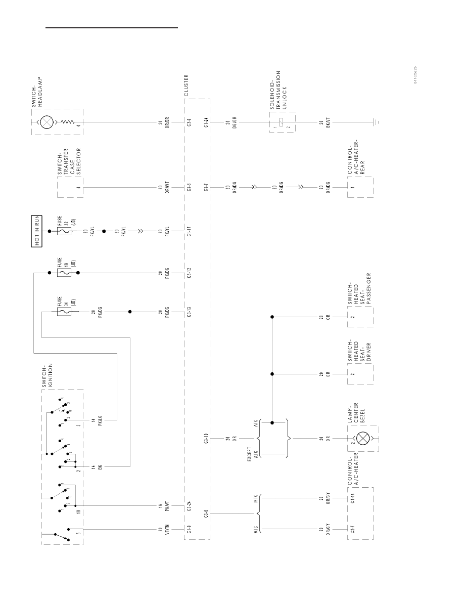
INSTRUMENT

CLUSTER

SYSTEM

SCHEMA

TIC

HB

INSTRUMENT CLUSTER - ELECTRICAL DIAGNOSTICS

8J - 33

CLUSTER

TABLE OF CONTENTS

page

page

CLUSTER

DESCRIPTION

. . . . . . . . . . . . . . . . . . . . . . . . . 35

OPERATION

. . . . . . . . . . . . . . . . . . . . . . . . . . . 39

DIAGNOSIS AND TESTING

INSTRUMENT CLUSTER

. . . . . . . . . . . . . . . . 42

REMOVAL

. . . . . . . . . . . . . . . . . . . . . . . . . . . . . 43

DISASSEMBLY

. . . . . . . . . . . . . . . . . . . . . . . . . 44

ASSEMBLY

. . . . . . . . . . . . . . . . . . . . . . . . . . . . 45

INSTALLATION

. . . . . . . . . . . . . . . . . . . . . . . . . 46

ABS INDICATOR

DESCRIPTION

. . . . . . . . . . . . . . . . . . . . . . . . . 47

OPERATION

. . . . . . . . . . . . . . . . . . . . . . . . . . . 48

AIRBAG INDICATOR

DESCRIPTION

. . . . . . . . . . . . . . . . . . . . . . . . . 48

OPERATION

. . . . . . . . . . . . . . . . . . . . . . . . . . . 49

BRAKE/PARK BRAKE INDICATOR

DESCRIPTION

. . . . . . . . . . . . . . . . . . . . . . . . . 49

OPERATION

. . . . . . . . . . . . . . . . . . . . . . . . . . . 50

DIAGNOSIS AND TESTING

BRAKE INDICATOR

. . . . . . . . . . . . . . . . . . . . 50

CHARGING INDICATOR

DESCRIPTION

. . . . . . . . . . . . . . . . . . . . . . . . . 51

OPERATION

. . . . . . . . . . . . . . . . . . . . . . . . . . . 51

CRUISE INDICATOR

DESCRIPTION

. . . . . . . . . . . . . . . . . . . . . . . . . 52

OPERATION

. . . . . . . . . . . . . . . . . . . . . . . . . . . 52

DOOR AJAR INDICATOR

DESCRIPTION

. . . . . . . . . . . . . . . . . . . . . . . . . 52

OPERATION

. . . . . . . . . . . . . . . . . . . . . . . . . . . 53

ENGINE TEMPERATURE GAUGE

DESCRIPTION

. . . . . . . . . . . . . . . . . . . . . . . . . 53

OPERATION

. . . . . . . . . . . . . . . . . . . . . . . . . . . 53

ENGINE TEMPERATURE INDICATOR

DESCRIPTION

. . . . . . . . . . . . . . . . . . . . . . . . . 54

OPERATION

. . . . . . . . . . . . . . . . . . . . . . . . . . . 55

ETC INDICATOR

DESCRIPTION

. . . . . . . . . . . . . . . . . . . . . . . . . 55

OPERATION

. . . . . . . . . . . . . . . . . . . . . . . . . . . 55

FOG LAMP INDICATOR

DESCRIPTION

. . . . . . . . . . . . . . . . . . . . . . . . . 56

OPERATION

. . . . . . . . . . . . . . . . . . . . . . . . . . . 56

FUEL GAUGE

DESCRIPTION

. . . . . . . . . . . . . . . . . . . . . . . . . 57

OPERATION

. . . . . . . . . . . . . . . . . . . . . . . . . . . 57

GATE AJAR INDICATOR

DESCRIPTION

. . . . . . . . . . . . . . . . . . . . . . . . . 58

OPERATION

. . . . . . . . . . . . . . . . . . . . . . . . . . . 58

GEAR SELECTOR INDICATOR

DESCRIPTION

. . . . . . . . . . . . . . . . . . . . . . . . . 59

OPERATION

. . . . . . . . . . . . . . . . . . . . . . . . . . . 59

HIGH BEAM INDICATOR

DESCRIPTION

. . . . . . . . . . . . . . . . . . . . . . . . . 60

OPERATION

. . . . . . . . . . . . . . . . . . . . . . . . . . . 60

LOW FUEL INDICATOR

DESCRIPTION

. . . . . . . . . . . . . . . . . . . . . . . . . 61

OPERATION

. . . . . . . . . . . . . . . . . . . . . . . . . . . 61

LOW OIL PRESSURE INDICATOR

DESCRIPTION

. . . . . . . . . . . . . . . . . . . . . . . . . 62

OPERATION

. . . . . . . . . . . . . . . . . . . . . . . . . . . 62

MALFUNCTION INDICATOR LAMP (MIL)

DESCRIPTION

. . . . . . . . . . . . . . . . . . . . . . . . . 62

OPERATION

. . . . . . . . . . . . . . . . . . . . . . . . . . . 63

ODOMETER

DESCRIPTION

. . . . . . . . . . . . . . . . . . . . . . . . . 63

OPERATION

. . . . . . . . . . . . . . . . . . . . . . . . . . . 64

SEATBELT INDICATOR

DESCRIPTION

. . . . . . . . . . . . . . . . . . . . . . . . . 65

OPERATION

. . . . . . . . . . . . . . . . . . . . . . . . . . . 65

STANDARD PROCEDURE

ENHANCED SEATBELT REMINDER

PROGRAMMING . . . . . . . . . . . . . . . . . . . . . . 66

SECURITY INDICATOR

DESCRIPTION

. . . . . . . . . . . . . . . . . . . . . . . . . 67

OPERATION

. . . . . . . . . . . . . . . . . . . . . . . . . . . 67

SERVICE 4WD INDICATOR

DESCRIPTION

. . . . . . . . . . . . . . . . . . . . . . . . . 68

OPERATION

. . . . . . . . . . . . . . . . . . . . . . . . . . . 68

SHIFT INDICATOR (TRANSFER CASE)

DESCRIPTION

4WD LOCK INDICATOR

. . . . . . . . . . . . . . . . . 69

4WD LOW INDICATOR

. . . . . . . . . . . . . . . . . 69

OPERATION

4WD LOCK INDICATOR

. . . . . . . . . . . . . . . . . 69

4WD LOW INDICATOR

. . . . . . . . . . . . . . . . . 70

SPEEDOMETER

DESCRIPTION

. . . . . . . . . . . . . . . . . . . . . . . . . 70

OPERATION

. . . . . . . . . . . . . . . . . . . . . . . . . . . 71

TACHOMETER

DESCRIPTION

. . . . . . . . . . . . . . . . . . . . . . . . . 71

OPERATION

. . . . . . . . . . . . . . . . . . . . . . . . . . . 72

TOW/HAUL INDICATOR

DESCRIPTION

. . . . . . . . . . . . . . . . . . . . . . . . . 72

OPERATION

. . . . . . . . . . . . . . . . . . . . . . . . . . . 72

TRACTION CONTROL INDICATOR

DESCRIPTION

. . . . . . . . . . . . . . . . . . . . . . . . . 73

OPERATION

. . . . . . . . . . . . . . . . . . . . . . . . . . . 73

TRANS TEMP INDICATOR

DESCRIPTION

. . . . . . . . . . . . . . . . . . . . . . . . . 74

OPERATION

. . . . . . . . . . . . . . . . . . . . . . . . . . . 74

8J - 34

CLUSTER

HB

TURN SIGNAL INDICATOR

DESCRIPTION

. . . . . . . . . . . . . . . . . . . . . . . . . 75

OPERATION

. . . . . . . . . . . . . . . . . . . . . . . . . . . 75

WASHER FLUID INDICATOR

DESCRIPTION

. . . . . . . . . . . . . . . . . . . . . . . . . 76

OPERATION

. . . . . . . . . . . . . . . . . . . . . . . . . . . 76

CLUSTER

DESCRIPTION

The instrument cluster (1) for this model is an Electro-
Mechanical Instrument Cluster (EMIC) that is located
in the instrument panel above the steering column
opening, directly in front of the driver. The remainder
of the EMIC, including the mounts and the electrical
connections, are concealed within the instrument
panel behind the cluster bezel (2). Besides analog
gauges and indicators, the EMIC module incorporates
a single blue-green digital Vacuum Fluorescent Dis-
play (VFD) unit for displaying odometer/trip odometer
information, engine hours, automatic transmission
gear selector position (PRNDL), several warning or
reminder indications and certain diagnostic informa-
tion. The instrument cluster for this model also
includes the hardware and software necessary to
serve as the electronic body control module and is
sometimes referred to as the Cab Compartment Node
or CCN.

The EMIC gauges and indicators are visible through a
dedicated opening in the cluster bezel on the instru-
ment panel and are protected by a clear plastic cluster
lens that is integral to a cluster lens, hood and mask
unit (3). Just behind the cluster lens is the cluster
hood and an integral cluster mask, which are con-
structed of molded black plastic. Two different masks
are used, one with silver rings and one with chrome
rings around the gauge openings. The cluster hood
serves as a visor and shields the face of the cluster
from ambient light and reflections to reduce glare,
while the cluster mask serves to separate and define
the individual gauges and indicators of the EMIC. A
black plastic odometer/trip odometer switch button
protrudes through dedicated holes in the cluster mask
and the cluster lens, located near the lower edge of
the cluster just to the left of the fuel gauge. The
molded plastic EMIC lens, hood and mask unit has
four integral mounting tabs, two each on the upper
and lower edges of the unit. These mounting tabs are
used to secure the EMIC to the molded plastic instru-
ment panel cluster carrier with four screws.

The rear of the cluster housing and the EMIC elec-
tronic circuitry are protected by a molded plastic rear
cover (1), which is secured to the cluster housing with
fourteen screws, while eight screws installed around
the outside perimeter of the rear cover secure it to the
cluster lens, hood and mask unit. The rear cover
includes clearance holes for the cluster connector receptacles. The connector receptacles on the back of the cluster

HB

CLUSTER

8J - 35

electronic circuit board connect the EMIC to the vehicle electrical system through three take outs with connectors
from the instrument panel wire harness.

Sandwiched between the rear cover and the lens, hood and mask unit is the cluster housing (2). The molded plastic
cluster housing serves as the carrier for the cluster circuit board and circuitry, the cluster connector receptacles, the
gauges, a Light Emitting Diode (LED) for each cluster indicator, the VFD unit, an audible tone transducer, an elec-
tro-luminescent lamp for general cluster illumination, the cluster overlay, the gauge pointers, the odometer/trip odom-
eter switch and the switch button.

The cluster overlay is a laminated plastic unit. The dark, visible, outer surface of the overlay is marked with all of the
gauge dial faces and graduations, but this layer is also translucent. The darkness of this outer layer prevents the
cluster from appearing cluttered or busy by concealing the cluster indicators that are not illuminated, while the trans-
lucence of this layer allows those indicators and icons that are illuminated to be readily visible. The underlying layer
of the overlay is opaque and allows light from the LED for each of the various indicators and an electro-luminescent
lamp behind it to be visible through the outer layer of the overlay only through predetermined stencil-like cutouts. A
rectangular opening in the overlay at the base of the tachometer dial faces has a smoked clear lens through which
the illuminated VFD unit can be viewed.

Several versions of the EMIC module are offered on this model. These versions accommodate all of the variations
of optional equipment and regulatory requirements for the various markets in which the vehicle will be offered. The
microprocessor-based EMIC utilizes integrated circuitry and information carried on the Controller Area Network
(CAN) data bus along with several hard wired analog and multiplexed inputs to monitor sensors and switches
throughout the vehicle. In response to those inputs, the internal circuitry and programming of the EMIC allow it to
control and integrate many electronic functions and features of the vehicle through both hard wired outputs and the
transmission of electronic message outputs to other electronic modules in the vehicle over the CAN data bus. (Refer
to 8 - ELECTRICAL/ELECTRONIC CONTROL MODULES/COMMUNICATION - DESCRIPTION - CAN BUS).

Besides typical instrument cluster gauge and indicator support, the electronic functions and features that the EMIC
supports or controls include the following:

Audible Warnings - The EMIC electronic circuit board is equipped with an audible tone transducer and pro-
gramming that allows it to provide various audible alerts to the vehicle operator, including chime tones and
beep tones. An electromechanical relay is also soldered onto the circuit board to produce audible clicks that
emulate the sound of a conventional turn signal or hazard warning flasher. (Refer to 8 - ELECTRICAL/CHIME/
BUZZER - DESCRIPTION).

Automatic Headlamps Control - On models equipped with optional automatic headlamps, the EMIC monitors
inputs from both the headlamp switch and a sun load sensor located on the top of the instrument panel to
provide automatic headlamps.

Brake Lamp Control - The EMIC provides electronic brake lamp request messages to the Front Control Mod-
ule (FCM) located on the Integrated Power Module (IPM) for brake lamp control, excluding control of the Cen-
ter High Mounted Stop Lamp (CHMSL), which remains controlled by a direct hard wired output of the brake
lamp switch.

Brake Transmission Shift Interlock Control - The EMIC monitors inputs from the brake lamp switch, ignition
switch, and the Transmission Range Sensor (TRS), then controls a high-side driver output to operate the
Brake Transmission Shift Interlock (BTSI) solenoid that locks and unlocks the automatic transmission gearshift
selector lever on the steering column.

Compass Mini Trip Computer Support - The EMIC provides support for the optional Compass Mini Trip
Computer (CMTC) by calculating average fuel economy, distance to empty and outside temperature values
and storing trip odometer and elapsed ignition on time data. The EMIC receives data and reset requests from
the CMTC and transmits the appropriate information for the CMTC to display using electronic messaging.

Electronic Transfer Case Interface - On vehicles equipped with an electronic four-wheel drive transfer case,
the EMIC monitors a hard wired multiplex input from the transfer case mode switch and then provides the
appropriate electronic data bus messages to the Front Control Module (FCM) located on the Integrated Power
Module (IPM) for transfer case control. After the transfer case shift is completed, the FCM provides an elec-
tronic message to the EMIC and the EMIC responds by activating the appropriate 4WD indicators within the
cluster or in the transfer case switch.

Enhanced Accident Response Support - The EMIC monitors an input from the Occupant Restraint Controller
(ORC) and, following an airbag deployment, will immediately disable the power lock output, unlock all doors by
activating the power unlock output, then enables the power lock output if the power lock switch input remains
inactive for two seconds. The EMIC also monitors an input from the Powertrain Control Module (PCM) to auto-
matically turn on the interior lighting after an airbag deployment event, ten seconds after the vehicle speed is

8J - 36

CLUSTER

HB


Content   ..  307  308  309  310   ..