Index Dodge Dodge Durango (HB) - service repair manual 2005 year
Search
Content .. 306 307 308 309 ..
Dodge Durango (HB). Manual - part 308
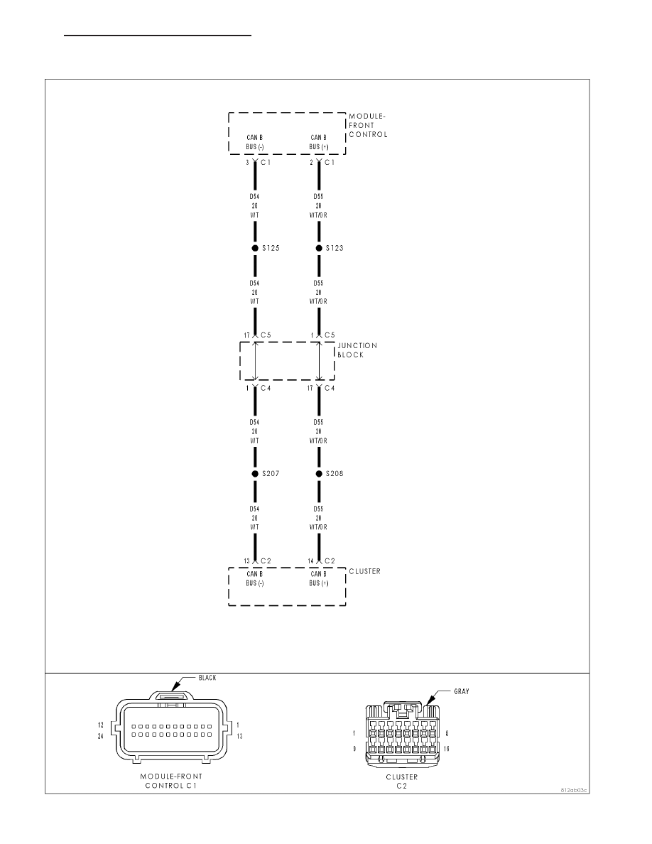
U0019–CAN B BUS
HB
INSTRUMENT CLUSTER - ELECTRICAL DIAGNOSTICS
8J - 29