Dodge Durango (HB). Manual - part 295
OPERATION
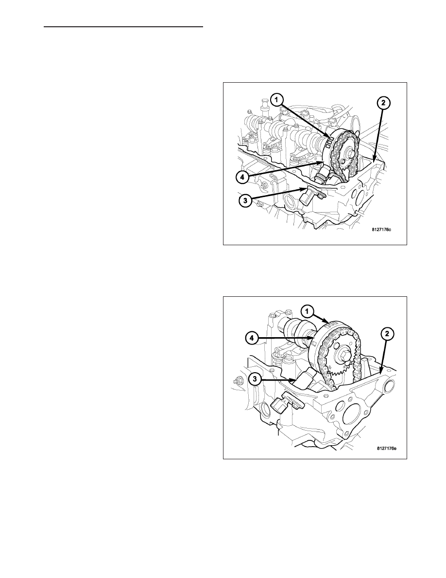
3.7L V-6
The Camshaft Position Sensor (CMP) sensor on the
3.7L V-6 engine (3) contains a hall effect device
referred to as a sync signal generator. A rotating target
wheel (tonewheel) for the CMP is located (4) at the
front of the camshaft for the right cylinder head (2).
This sync signal generator detects notches (1) located
on a tonewheel. As the tonewheel rotates, the notches
pass through the sync signal generator. The signal
from the CMP sensor is used in conjunction with the
Crankshaft Position Sensor (CKP) to differentiate
between fuel injection and spark events. It is also
used to synchronize the fuel injectors with their
respective cylinders.
When the leading edge of the tonewheel notch enters
the tip of the CMP, the interruption of magnetic field
causes the voltage to switch high, resulting in a sync
signal of approximately 5 volts.
When the trailing edge of the tonewheel notch leaves
then tip of the CMP, the change of the magnetic field
causes the sync signal voltage to switch low to 0 volts.
4.7L V-8
The CMP sensor on the 4.7L engine contains a hall
effect device called a sync signal generator to gener-
ate a fuel sync signal. This sync signal generator
detects notches located on a tonewheel. The tone-
wheel (4) is located at the front of the camshaft for the
right cylinder head (2). As the tonewheel rotates, the
notches (1) pass through the sync signal generator.
The pattern of the notches (viewed counter-clockwise
from front of engine) is: 1 notch, 2 notches, 3 notches,
3 notches, 2 notches 1 notch, 3 notches and 1 notch.
The signal from the CMP sensor is used in conjunc-
tion with the crankshaft position sensor to differentiate
between fuel injection and spark events. It is also
used to synchronize the fuel injectors with their
respective cylinders.
HB
IGNITION SYSTEM - SERVICE INFORMATION
8I - 11