Dodge Durango (HB). Manual - part 296


  Index      Dodge     Dodge Durango (HB) - service repair manual 2005 year


Search            


Content   ..  294  295  296  297   ..


Dodge Durango (HB). Manual - part 296


4. Install mounting bolt and tighten. Refer to Torque Specifications.

5. Connect electrical connector to sensor.
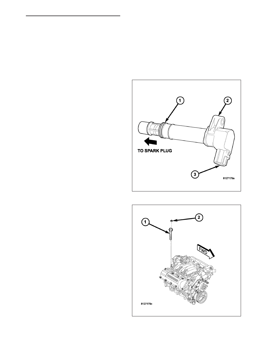
COIL-IGNITION

DESCRIPTION

3.7L V-6

The 3.7L V-6 engine uses 6 dedicated, and individu-
ally fired coil for each spark plug (2).

Each coil (1) is mounted directly into the cylinder head
and onto the top of each spark plug.

HB

IGNITION SYSTEM - SERVICE INFORMATION

8I - 15

4.7L V-8

The 4.7L V–8 engine uses 8 dedicated, and individu-
ally fired coil (1) for each spark plug. Each coil is
mounted directly to the top of each spark plug.

5.7L V-8

The 5.7L V–8 engine uses 8 dedicated, and individu-
ally fired coil (1) for each pair of spark plugs.

8I - 16

IGNITION SYSTEM - SERVICE INFORMATION

HB

Each coil (5) is mounted directly to the top of each
spark plug. Each coil is bolted (6) to the valve cover.

OPERATION

3.7L V-6

Battery voltage is supplied to the 6 individual ignition coils from the ASD relay. The Powertrain Control Module
(PCM) opens and closes each ignition coil ground circuit at a determined time for ignition coil operation.

Base ignition timing is not adjustable. By controlling the coil ground circuit, the PCM is able to set the base
timing and adjust the ignition timing advance. This is done to meet changing engine operating conditions.

The ignition coil is not oil filled. The windings are embedded in an epoxy compound. This provides heat and vibra-
tion resistance that allows the ignition coil to be mounted on the engine.

Because of coil design, spark plug cables (secondary cables) are not used with the 3.7L V-6 engine.

4.7L V-8

Battery voltage is supplied to the 8 individual ignition coils from the ASD relay. The Powertrain Control Module
(PCM) opens and closes each ignition coil ground circuit at a determined time for ignition coil operation.

Base ignition timing is not adjustable. By controlling the coil ground circuit, the PCM is able to set the base
timing and adjust the ignition timing advance. This is done to meet changing engine operating conditions.

The ignition coil is not oil filled. The windings are embedded in an epoxy compound. This provides heat and vibra-
tion resistance that allows the ignition coil to be mounted on the engine.

Because of coil design, spark plug cables (secondary cables) are not used with the 4.7L V-8 engine.

5.7L V-8

The ignition system is controlled by the Powertrain Control Module (PCM) on all engines.

A “wasted spark” system is used on the 5.7L engine combining paired, or dual-firing coils, and 2 spark plugs per
cylinder. The coils and spark plugs are connected with paired, secondary high-voltage cables.

Each cylinder is equipped with 1 dual-output coil. Meaning one coil mounts directly over one of the dual spark plugs
for 1 high-voltage output. A second high-voltage output is supplied directly from the same coil (using a plug cable)
to one of the dual spark plugs on a corresponding (paired) cylinder on the opposite cylinder bank.

HB

IGNITION SYSTEM - SERVICE INFORMATION

8I - 17

Each coil fires 2 spark plugs simultaneously on each of the cylinder banks (one cylinder on compression stroke and
one cylinder on exhaust stroke). EXAMPLE : When the #1 cylinder is on compression stroke and ready for spark,
the #1 coil will fire one of the dual spark plugs on the #1 cylinder (directly below the coil). The other dual spark plug
on the #1 cylinder will be fired by the #6 coil. At the same time, the #1 coil will fire a “wasted spark” to one of the
dual spark plugs at the #6 cylinder as coil #6 also fires a “wasted spark” to one of the dual spark plugs at the #6
cylinder.

The firing order is paired at cylinders 1/6, 2/3, 4/7, 5/8. Basic cylinder firing order is 1–8–4–3–6–5–7–2.

Battery voltage is supplied to all of the ignition coils positive terminals from the ASD relay. If the PCM does not see
a signal from the crankshaft and camshaft sensors (indicating the ignition key is ON but the engine is not running),
it will shut down the ASD circuit.

Base ignition timing is not adjustable on the 5.7L V-8 engine. By controlling the coil ground circuits, the PCM is
able to set the base timing and adjust the ignition timing advance. This is done to meet changing engine operating
conditions.

The PCM adjusts ignition timing based on inputs it receives from:

The engine coolant temperature sensor

The crankshaft position sensor (engine speed)

The camshaft position sensor (crankshaft position)

The manifold absolute pressure (MAP) sensor

The throttle position sensor

Transmission gear selection

REMOVAL

3.7L V-6

An individual ignition coil is used for each spark plug
(2). The coil fits into machined holes in the cylinder
head. A mounting stud/nut secures each coil to the top
of the intake manifold. The bottom of the coil is
equipped with a rubber boot to seal the spark plug to
the coil. Inside each rubber boot is a spring. The
spring is used for a mechanical contact between the
coil and the top of the spark plug. These rubber boots
and springs are a permanent part of the coil and are
not serviced separately. An o-ring (1) is used to seal
the coil at the opening into the cylinder head.

1. Depending on which coil is being removed, the

throttle body air intake tube or intake box may
need to be removed to gain access to coil.

2. Disconnect electrical connector from coil by push-

ing downward on release lock on top of connector
and pull connector from coil.

3. Clean area at base of coil with compressed air

before removal.

8I - 18

IGNITION SYSTEM - SERVICE INFORMATION

HB


Content   ..  294  295  296  297   ..