Dodge Durango (HB). Manual - part 293
B2100-IGNITION RUN/START INPUT CIRCUIT PERFORMANCE (CONTINUED)
For a complete wiring diagram Refer to Section 8W.
•
When Monitored:
With the ignition on.
•
Set Condition:
The Front Control Module will set this DTC if the CAN bus message and the hardwired ignition switch circuit
do not match the position of the ignition switch.
Possible Causes
JUNCTION BLOCK FUSE #18
(F202) FUSED IGNITION SWITCH OUTPUT CIRCUIT OPEN
(F202) FUSED IGNITION SWITCH OUTPUT CIRCUIT SHORTED TO GROUND
FRONT CONTROL MODULE
Diagnostic Test
1.
CHECK FOR ACTIVE DTC
With the scan tool, read the active DTC’s.
Cycle the ignition switch from off to on, leaving the ignition on for a minimum of 90 seconds.
With the scan tool, read the active DTC’s.
Does the scan tool display this DTC as active?
Yes
>> Go To 2
No
>> If the DTC is stored, check for an intermittent condition. Visually inspect the related wiring harness con-
nectors. Look for broken, bent, pushed out, or corroded terminals.
2.
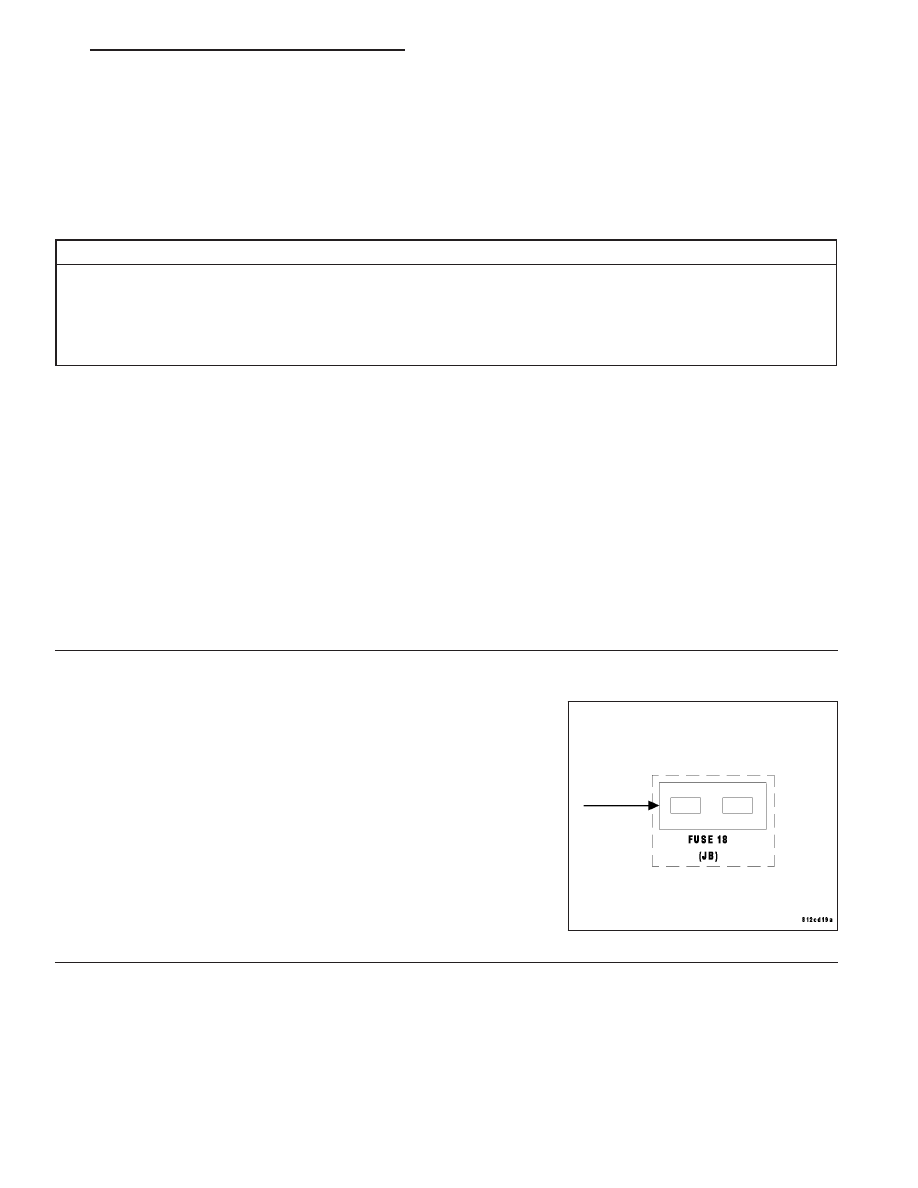
INSPECT JUNCTION BLOCK FUSE #18
Turn the ignition off.
Remove and inspect Junction Block Fuse #18.
Is the fuse open?
Yes
>> Replace fuse and retest. If fuse continues to fail inspect
the wiring between the Junction Block and the Front Con-
trol Module for a short to ground.
Perform BODY VERIFICATION TEST – VER 1.
No
>> Go To 3
HB
IGNITION SYSTEM - ELECTRICAL DIAGNOSTICS
8I - 3