Index Dodge Dodge Durango (HB) - service repair manual 2005 year
Search
Content .. 227 228 229 230 ..
Dodge Durango (HB). Manual - part 229
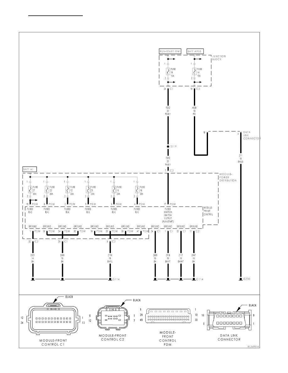
*NO RESPONSE FROM FCM
HB
ELECTRONIC CONTROL MODULES - ELECTRICAL DIAGNOSTICS
8E - 137