Dodge Durango (HB). Manual - part 227
*NO RESPONSE FROM CCN (CONTINUED)
2.
(A924) (A920) (A117) FUSED B(+) CIRCUITS OPEN OR SHORTED
Turn the ignition off.
Disconnect the Cluster harness connectors.
Using a 12-volt test light connected to ground, check each (A924)
(A920) (A117) Fused B(+) circuit.
Does the test light illuminate brightly for each circuit?
Yes
>> Go To 3
No
>> Repair the (A924) (A920) (A117) Fused B(+) circuit for an
open or short.
Perform BODY VERIFICATION TEST - VER 1.
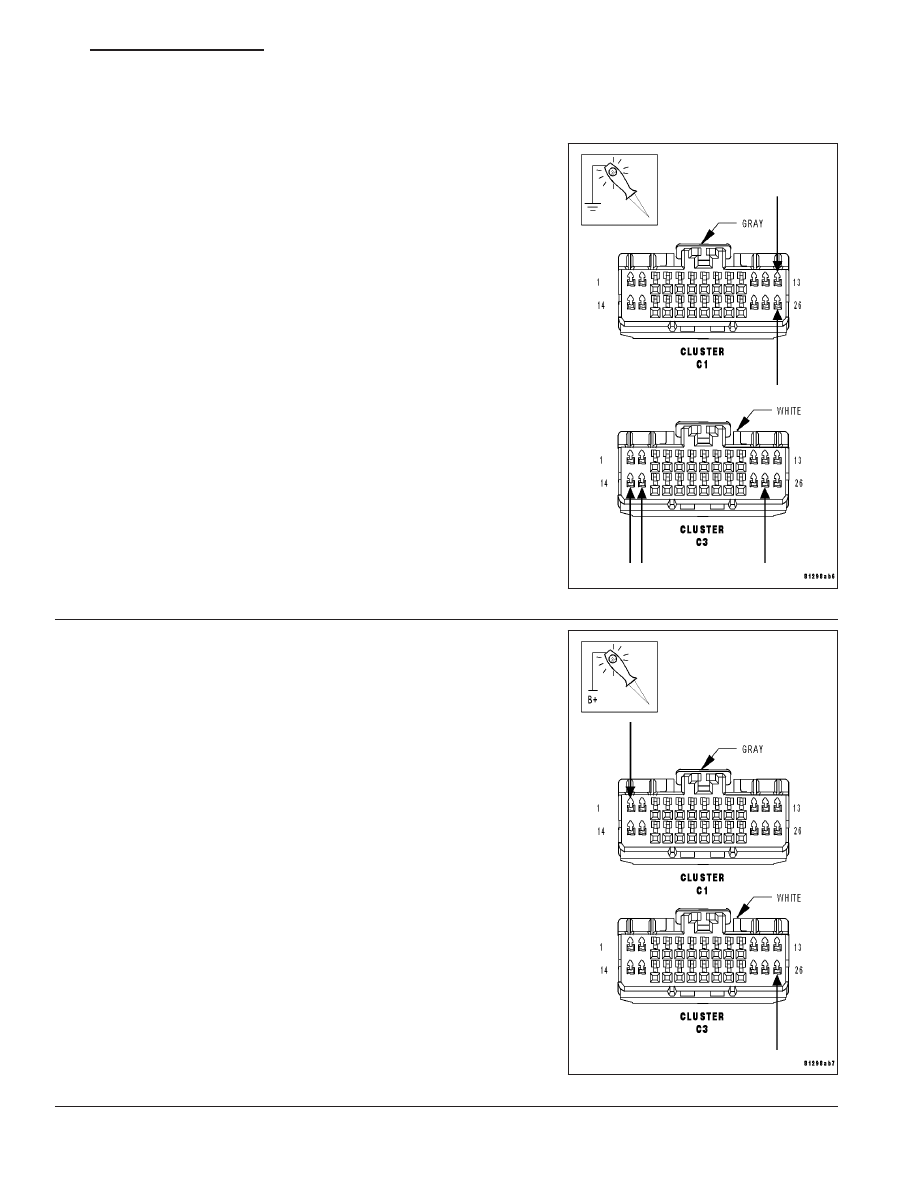
3.
(Z946) (Z948) GROUND CIRCUITS OPEN
Using a 12-volt test light connected to 12-volts, check each (Z946)
(Z948) ground circuit.
Does the test light illuminate brightly for each circuit?
Yes
>> Go To 4
No
>> Repair the (Z946) (Z948) ground circuit for an open.
Perform BODY VERIFICATION TEST - VER 1.
HB
ELECTRONIC CONTROL MODULES - ELECTRICAL DIAGNOSTICS
8E - 129