Dodge Durango (HB). Manual - part 228


  Index      Dodge     Dodge Durango (HB) - service repair manual 2005 year


Search            


Content   ..  226  227  228  229   ..


Dodge Durango (HB). Manual - part 228


*NO RESPONSE FROM DDM (CONTINUED)
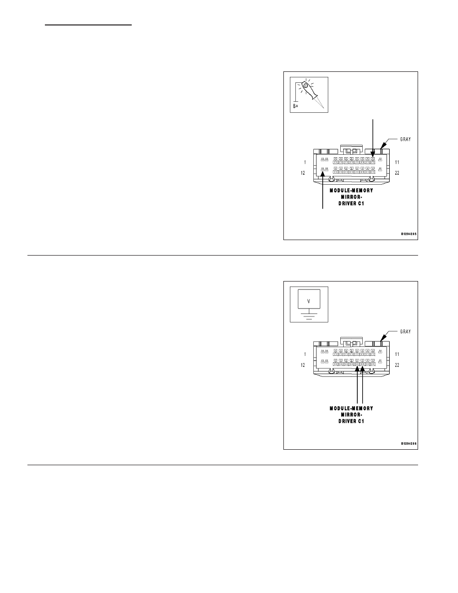
3.

(Z940) GROUND CIRCUIT OPEN

Using a 12-volt test light connected to 12-volts, check each (Z940)
ground circuit.

Does the test light illuminate brightly for each circuit?

Yes

>> Go To 4

No

>> Repair the (Z940) ground circuit for an open.

Perform BODY VERIFICATION TEST - VER 1.

4.

(D55) AND (D54) CAN B BUS CIRCUITS OPEN

NOTE: One open circuit will not cause this condition.
Measure the voltage between the (D54) CAN B Bus (-) circuit and
ground.

Measure the voltage between the (D55) CAN B Bus (+) circuit and
ground.

Is there any voltage present on either circuit?

Yes

>> Replace the Driver Memory Mirror Module in accordance

with the service information.

Perform BODY VERIFICATION TEST - VER 1.

No

>> Repair the (D55) and (D54) CAN B Bus circuits for an

open. Inspect the connector for damage.

Perform BODY VERIFICATION TEST - VER 1.

HB

ELECTRONIC CONTROL MODULES - ELECTRICAL DIAGNOSTICS

8E - 133

*NO RESPONSE FROM EOM

8E - 134

ELECTRONIC CONTROL MODULES - ELECTRICAL DIAGNOSTICS

HB

*NO RESPONSE FROM EOM (CONTINUED)

For a complete wiring diagram Refer to Section 8W.

Possible Causes

(A926) FUSED B(+) CIRCUIT OPEN OR SHORTED

(Z957) GROUND CIRCUIT OPEN

(D55) AND (D54) CAN B BUS CIRCUITS OPEN

ELECTRONIC OVERHEAD MODULE

Diagnostic Test

1.

TEST FOR INTERMITTENT CONDITION

Turn the ignition on.

NOTE: Ensure the IOD fuse is installed and battery voltage is between 10.0 and 16.0 volts.
With the scan tool, select ECU view.

NOTE: A red X will be next to the module that is not communicating, indicating that the module is not active
on the Bus network. A green check indicates that the module is active on the Bus network.

Does the scan tool display a red X next to the module?

Yes

>> Go To 2

No

>> The no response condition is not present at this time. Using the wiring diagram/schematic as a guide,

inspect the wiring for chafed, pierced, pinched, and partially broken wires and the wiring harness con-
nectors for broken, bent , pushed out, and corroded terminals.

2.

(A926) FUSED B(+) CIRCUIT OPEN OR SHORTED

Turn the ignition off.

Disconnect the Electronic Overhead Module harness connector.

Using a 12-volt test light connected to ground, check the (A926) Fused
B(+) circuit.

Does the test light illuminate brightly?

Yes

>> Go To 3

No

>> Repair the (A926) Fused B(+) circuit for an open or short.

Perform BODY VERIFICATION TEST - VER 1.

HB

ELECTRONIC CONTROL MODULES - ELECTRICAL DIAGNOSTICS

8E - 135

*NO RESPONSE FROM EOM (CONTINUED)

3.

(Z957) GROUND CIRCUIT OPEN

Using a 12-volt test light connected to 12-volts, check the (Z957)
ground circuit.

Does the test light illuminate brightly?

Yes

>> Go To 4

No

>> Repair the (Z957) ground circuit for an open.

Perform BODY VERIFICATION TEST - VER 1.

4.

(D55) AND (D54) CAN B BUS CIRCUITS OPEN

NOTE: One open circuit will not cause this condition.
Measure the voltage between the (D54) CAN B Bus (-) circuit and
ground.

Measure the voltage between the (D55) CAN B Bus (+) circuit and
ground.

Is there any voltage present on either circuit?

Yes

>> Replace the Electronic Overhead Module in accordance

with the service information.

Perform BODY VERIFICATION TEST - VER 1.

No

>> Repair the (D55) and (D54) CAN B Bus circuits for an

open. Inspect the connector for damage.

Perform BODY VERIFICATION TEST - VER 1.

8E - 136

ELECTRONIC CONTROL MODULES - ELECTRICAL DIAGNOSTICS

HB


Content   ..  226  227  228  229   ..