Content .. 1537 1538 1539 1540 ..
Dodge Durango (HB). Manual - part 1539
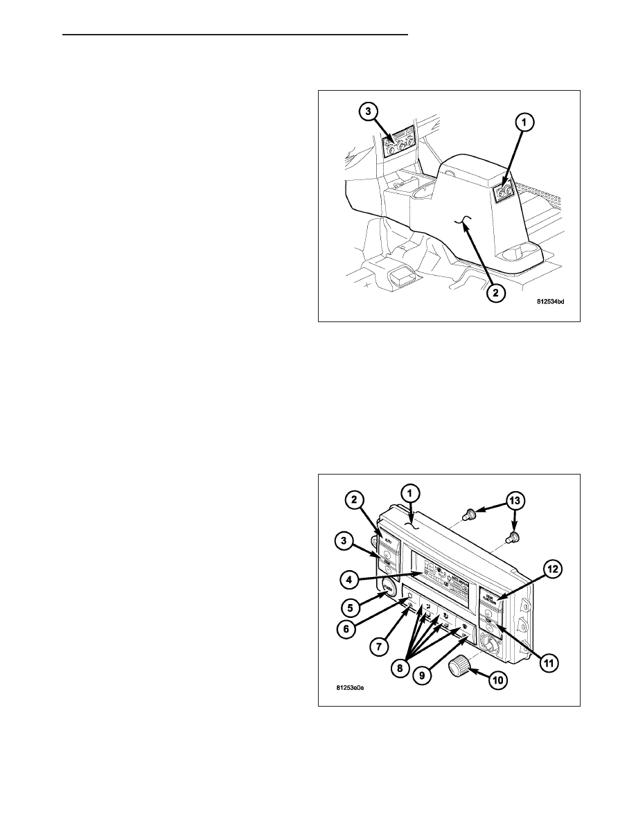
REAR CONTROL PANEL
The rear A/C-heater control (1) is located at the rear
of the center floor console (2) and allows intermediate
seat passengers to adjust rear air distribution, temper-
ature and blower motor speed when the center control
knob on the front A/C-heater control (3) is set to the
Rear position (Refer to 24 - HEATING & AIR CONDI-
TIONING/CONTROLS
-
REAR/CONTROL-A/C
HEATER - DESCRIPTION).
AUTOMATIC SINGLE ZONE WITH REAR HEAT AND A/C
The A/C-heater control (1) for the automatic temperature control (ATC) single zone front and rear heating-A/C sys-
tem allows both the front and intermediate seat passengers the ability to automatically or manually regulate air tem-
perature as well as fan speed and provides floor outlets near the right rear door and overhead outlets at each rear
intermediate outboard seating position. Primary control for the rear blower motor is on the front A/C-heater control.
All controls are identified by ISO graphic symbols.
FRONT CONTROL PANEL
The front A/C-heater control and integral computer is
located in the instrument panel and contains:
•
a push button Auto mode control (2).
•
a rocker switch control that selects comfort tem-
peratures from 15° to 29° C (60° to 85° F) (3).
Comfort temperatures are shown in the vacuum-
flourescent (VF) digital display (4). If the set tem-
perature is 15° C (60° F) and down (–) is
pressed, the A/C-heater control will attempt to
achieve the lowest temperature possible, but the
display will show LO. If the set temperature is
29° C (85° F) and up (+) is pressed, the A/C-
heater control will attempt to achieve the highest
temperature possible, but the display will show
HIGH. Temperatures can be displayed in either
Metric or Fahrenheit, which is selected from the
overhead console.
•
a push button on/off control which allows the sys-
tem to be completely turned off (5). The display
is blank when the heater-A/C system is off, except for the electric backlight (EBL) symbol, if EBL is on.
•
a push button A/C on/off control (6). An ISO Snowflake symbol appears in the display when the A/C system is
in operation, whether under manual or automatic control.
•
a push button air recirculation control (7). A ISO Recirculation symbol appears in the display when the button
is pressed, or when the system exceeds 80 percent circulated air under automatic control due to high A/C
demand.
HB
CONTROLS - FRONT
24 - 349