Dodge Durango (HB). Manual - part 1538


  Index      Dodge     Dodge Durango (HB) - service repair manual 2005 year


Search            


Content   ..  1536  1537  1538  1539   ..


Dodge Durango (HB). Manual - part 1538


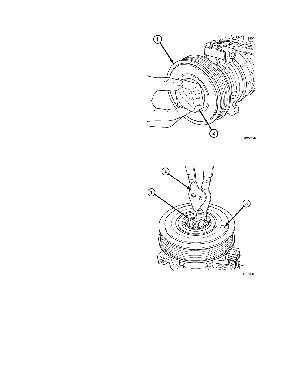
CAUTION: When installing the pulley and bearing
assembly, DO NOT mar the friction surfaces of the
pulley or premature failure of the clutch will result.

4. Install the pulley and bearing assembly (1) onto the

front cover of the A/C compressor. If necessary, tap
the pulley gently with a block of wood (2) placed on
the pulley friction surface.

CAUTION: The snap ring must be fully and prop-
erly seated in the groove or it will vibrate out,
resulting in a clutch failure and severe damage to
the A/C compressor.

NOTE: A new snap ring must be used to secure
the pulley and bearing assembly to the A/C com-
pressor. The bevel side of the snap ring must face
outward.

5. Using snap ring pliers (Special Tool C-4574 or

equivalent) (2), install the external snap ring (1)
that secures the pulley and bearing assembly (3) to
the front cover of the A/C compressor. Be certain
that the snap ring is fully and properly seated in the
groove.

HB

CONTROLS - FRONT

24 - 345

6. If the original clutch plate (2) and pulley and bear-

ing assembly are to be reused, reinstall the original
shim(s) (3) on the compressor shaft (1) against the
shoulder. If a new clutch plate and/or pulley and
bearing assembly are being used, install a trial
stack of shims 2.54 mm (0.010 in.) thick on the
compressor shaft against the shoulder.

7. Install the clutch plate (2) onto the compressor

shaft.

8. Install the compressor shaft bolt (1). Tighten the

bolt to 19 N·m (168 in. lbs.).

NOTE: The shims may compress after tightening
the shaft bolt. Check the air gap in four or more
places to verify the air gap is correct. Spin the pul-
ley before performing a final check of the air gap.

9. With the clutch plate assembled tight against the

shim(s), measure the air gap between the clutch
plate and the pulley and bearing assembly faces
with a feeler gauge. The air gap should be between
specifications (Refer to 24 - HEATING & AIR CON-
DITIONING - SPECIFICATIONS). If the proper air
gap is not obtained, add or subtract shims as
needed until the desired air gap is obtained.

10. Install the bolts that secure the A/C compressor to

the engine (Refer to 24 - HEATING & AIR CON-
DITIONING/PLUMBING/COMPRESSOR-A/C

-

INSTALLATION).

11. Connect the engine wire harness connector to the A/C compressor clutch coil.

12. Install the accessory drive belt (Refer to 7 - COOLING/ACCESSORY DRIVE/BELTS-DRIVE - INSTALLATION).

13. Reconnect the negative battery cable.

24 - 346

CONTROLS - FRONT

HB

CONTROL-A/C HEATER

DESCRIPTION

MANUAL SINGLE ZONE

The A/C-heater control (1) for the manual temperature control (MTC) single zone heating-A/C system allows one
temperature setting for the entire vehicle. All controls are identified by ISO graphic symbols.

The A/C-heater control and integral computer is
located in the instrument panel and contains:

a rotary control knob for rear window washer
operation and rear window wiper speed selection
(2).

a slider control knob for temperature control of
the discharged air (3).

a rotary control knob for fan speed selection and
turning the heater-A/C system off (4).

a rotary control knob for mode control of the dis-
charged air (5).

a push button A/C on/off control (6). The Snow-
flake button contains an LED that illuminates
when the A/C system is in operation.

a push button rear window defogger on/off con-
trol (7). The button contains an LED that illumi-
nates when the rear window defogger system is
in operation.

The A/C-heater control cannot be repaired and, if
faulty or damaged, it must be replaced. The illumination lamps (8) and control knobs are available for service
replacement.

The A/C-heater control for the manual single zone heating and A/C system is diagnosed using a scan tool. Refer to
24 - HVAC Electrical Diagnostics for more information.

The A/C-heater control utilizes integrated circuitry and information carried on the controller area network (CAN) B
bus to monitor many sensors and switch inputs throughout the vehicle. In response to those inputs, the internal
circuitry and programming of the A/C-heater control allows it to control electronic functions and features of the MTC
heating-A/C system.

The inputs received by the A/C-heater control of the MTC heating-A/C system on the CAN B bus are as follows:

Dimming

Refrigerant Pressure

Vehicle Identification Number

Vehicle Odometer

Engine Coolant Temperature

Ambient Air Temperature

Vehicle Speed

The messages broadcasted by the A/C-heater control of the MTC heating-A/C system on the CAN B bus are as
follows:

A/C Request

A/C Select

Rear Window Defogger (EBL) Request

Rear Washer Request

Rear Wiper Request

HB

CONTROLS - FRONT

24 - 347

MANUAL SINGLE ZONE WITH REAR HEAT AND A/C

The A/C-heater control (1) for the manual temperature control (MTC) single zone front and rear heating-A/C system
allows both the front and intermediate seat passengers the ability to regulate air temperature as well as fan speed
and provides floor outlets near the right rear door and overhead outlets at each intermediate outboard seating posi-
tion. Primary control for the rear blower motor is on the front A/C-heater control. All controls are identified by ISO
graphic symbols.

FRONT CONTROL PANEL

The front A/C-heater control and integral computer is
located in the instrument panel and contains:

a rotary control knob for rear window washer
operation and rear window wiper speed selection
(2).

a slider control knob for temperature control of
the discharged air (3).

a rotary control knob for fan speed selection and
turning the heater-A/C system off (4).

a rotary control knob for rear fan speed selection
and turning the rear heater-A/C system off (5).

a rotary control knob for mode control of the dis-
charged air (6).

a push button A/C on/off control (7). The Snow-
flake button contains an LED that illuminates
when the A/C system is in operation.

a push button rear window defogger on/off con-
trol (8). The button contains an LED that illumi-
nates when the rear window defogger system is
in operation.

The front A/C-heater control cannot be repaired and, if faulty or damaged, it must be replaced. The illumination
lamps (9) and control knobs are available for service replacement.

The A/C-heater control for the MTC single zone heating-A/C system is diagnosed using a scan tool. Refer to 24 -
HVAC Electrical Diagnostics for more information.

The A/C-heater control utilizes integrated circuitry and information carried on the controller area network (CAN) B
bus to monitor many sensors and switch inputs throughout the vehicle. In response to those inputs, the internal
circuitry and programming of the A/C-heater control allows it to control electronic functions and features of the MTC
heating-A/C system.

The inputs received by the A/C-heater control of the MTC heating-A/C system on the CAN B bus are as follows:

Dimming

Refrigerant Pressure

Vehicle Identification Number

Vehicle Odometer

Engine Coolant Temperature

Ambient Air Temperature

Vehicle Speed

The messages broadcasted by the A/C-heater control of the MTC heating-A/C system on the CAN B bus are as
follows:

A/C Request

A/C Select

Rear Window Defogger (EBL) Request

Rear Washer Request

Rear Wiper Request

24 - 348

CONTROLS - FRONT

HB


Content   ..  1536  1537  1538  1539   ..