Dodge Durango (HB). Manual - part 1536


  Index      Dodge     Dodge Durango (HB) - service repair manual 2005 year


Search            


Content   ..  1534  1535  1536  1537   ..


Dodge Durango (HB). Manual - part 1536


The mode door actuators are diagnosed using a scan tool. Refer to 24 - HVAC Electrical Diagnostics for more
information.

REMOVAL

WARNING: On vehicles equipped with airbags, disable the airbag system before attempting any steering
wheel, steering column, or instrument panel component diagnosis or service. Disconnect and isolate the
battery negative (ground) cable, then wait two minutes for the airbag system capacitor to discharge before
performing further diagnosis or service. This is the only sure way to disable the airbag system. Failure to
take the proper precautions could result in accidental airbag deployment and possible personal injury or
death.

1. Disconnect and isolate the negative battery cable.

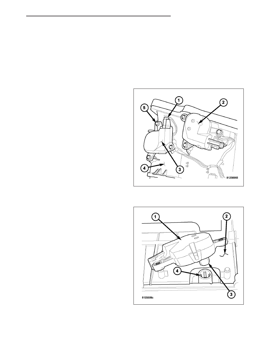
2. Remove the screws (5) that secure the panel door

actuator (2) and the floor/defrost door actuator (3)
located on the driver side end of the HVAC housing
(4) as required.

3. Disconnect the HVAC wire harness connector (1)

from the panel door actuator and the floor/defrost
door actuator as required.

4. Remove the mode door actuator(s) from the HVAC

housing.

INSTALLATION

1. Position the mode door actuator(s) (1) onto the

driver side end of the HVAC housing as required. If
necessary, rotate the actuator slightly to align the
splines on the actuator output shaft with those in
the mode-air door linkage.

HB

CONTROLS - FRONT

24 - 337

2. Install the screws (5) that secure the panel door

actuator (2) and the floor/defrost door actuator (3)
to the HVAC housing (4) as required. Tighten the
screws to 2 N·m (17 in. lbs.).

3. Connect the HVAC wire harness connector (1) to

the mode door actuator(s) as required.

4. Reconnect the negative battery cable.

5. Initiate the Actuator Calibration function using a

scan tool. Refer to HVAC System Test, found in 24
- HVAC - Electrical Diagnostics.

ACTUATOR-RECIRCULATION DOOR

DESCRIPTION

The recirculation door actuator (1) is a reversible, 12
volt direct current (DC), servo motor. The recirculation
door actuator is located on the left side of the HVAC
air inlet housing. The recirculation door actuator is
interchangeable with the actuators for the blend-air
door and the mode-air doors. Each actuator is con-
tained within an identical black molded plastic housing
with an integral wire connector receptacle. Three inte-
gral mounting tabs allow the actuator to be secured to
the air inlet housing. Each actuator also has an iden-
tical output shaft with splines that connects it to the
recirculation-air door. The recirculation door actuator
does not require mechanical indexing to the recircula-
tion-air door, as it is electronically calibrated by the
A/C-heater control.

OPERATION

The recirculation door actuator is connected to the A/C-heater control through the vehicle electrical system by a
dedicated two-wire lead and connector of the HVAC wire harness. The recirculation door actuator can move the
recirculation-air door in two directions. When the A/C-heater control pulls the voltage on one side of the motor con-
nection high and the other connection low, the recirculation-air door will move in one direction. When the A/C-heater
control reverses the polarity of the voltage to the motor, the recirculation-air door moves in the opposite direction.

When the A/C-heater control makes the voltage to both connections high or both connections low, the recirculation-
air door stops and will not move. The A/C-heater control uses a pulse-count positioning system to monitor the oper-
ation and relative position of the recirculation door actuator and the recirculation-air door. The A/C-heater control
learns the recirculation-air door stop positions during the calibration procedure and will store a diagnostic trouble
code (DTC) for any problems it detects in the recirculation door actuator circuits.

The recirculation door actuator cannot be adjusted or repaired and, if faulty or damaged, it must be replaced.

24 - 338

CONTROLS - FRONT

HB

The recirculation door actuator is diagnosed using a scan tool. Refer to 24 - HVAC Electrical Diagnostics for more
information.

REMOVAL

1. Disconnect and isolate the negative battery cable.

2. Remove the HVAC assembly (Refer to 24 - HEAT-

ING

&

AIR

CONDITIONING/DISTRIBUTION

-

FRONT/HOUSING-HVAC - REMOVAL).

3. Remove the air inlet housing (1) from the HVAC

housing and place it on a workbench (Refer to 24 -
HEATING & AIR CONDITIONING/DISTRIBUTION -
FRONT/HOUSING-HVAC - DISASSEMBLY).

4. Remove the screws (2) that secure the recircula-

tion door actuator (3) to the HVAC air inlet housing.

5. Remove the recirculation door actuator from the

HVAC air inlet housing.

INSTALLATION

1. Position the recirculation door actuator (1) to the

HVAC air inlet housing. If necessary, rotate the
actuator slightly to align the splines on the actuator
output shaft with those in the recirculation-air door
linkage.

HB

CONTROLS - FRONT

24 - 339

2. Install the screws (2) that secure the recirculation

door actuator (3) to the HVAC air inlet housing (1).
Tighten the screws to 2 N·m (17 in. lbs.).

3. Install the air inlet housing to the HVAC housing

(Refer to 24 - HEATING & AIR CONDITIONING/
DISTRIBUTION

-

FRONT/HOUSING-HVAC

-

ASSEMBLY).

4. Install the HVAC housing (Refer to 24 - HEATING

& AIR CONDITIONING/DISTRIBUTION - FRONT/
HOUSING-HVAC - INSTALLATION).

5. Reconnect the negative battery cable.

6. Initiate the Actuator Calibration function using a

scan tool. Refer to HVAC System Test, found in 24
- HVAC - Electrical Diagnostics.

CLUTCH-A/C COMPRESSOR

DESCRIPTION

The A/C compressor clutch assembly consists of a
stationary electromagnetic A/C clutch field coil (4), pul-
ley bearing and pulley assembly (3), clutch plate (2)
and shims (7). These components provide the means
to engage and disengage the A/C compressor from
the engine accessory drive belt.

The A/C clutch field coil and the pulley bearing and
pulley assembly are both retained on the nose of the
A/C compressor with snap rings (5 and 6). The clutch
plate is splined to the compressor shaft and secured
with a bolt (1).

OPERATION

The A/C compressor clutch components provide the means to engage and disengage the A/C compressor from the
engine accessory drive belt. When the electromagnetic A/C clutch field coil is energized, it magnetically draws the
clutch plate into contact with the clutch pulley and drives the compressor shaft. When the coil is not energized, the
pulley freewheels on the clutch hub bearing, which is part of the pulley assembly.

The A/C compressor clutch engagement is controlled by the following components:

A/C-heater control in the passenger compartment

A/C pressure transducer on the A/C discharge line

Powertrain control module (PCM) in the engine compartment

A/C clutch relay in the power distribution center (PDC)

The A/C compressor clutch components cannot be repaired and, if faulty or damaged, they must be replaced.

24 - 340

CONTROLS - FRONT

HB


Content   ..  1534  1535  1536  1537   ..