Content .. 1532 1533 1534 1535 ..
Dodge Durango (HB). Manual - part 1534
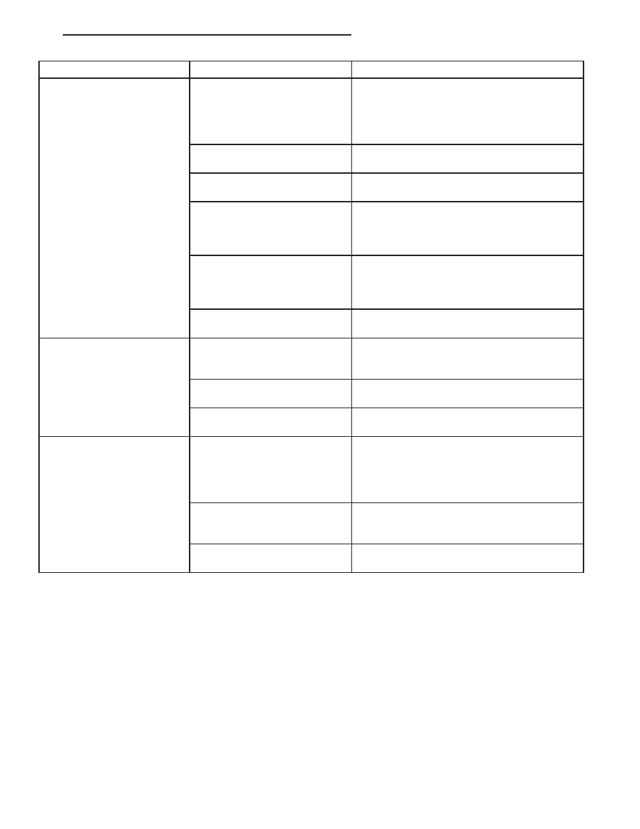
Condition
Possible Causes
Correction
The low side pressure is
normal or slightly high, and
the high side pressure is too
high.
1. A/C condenser air flow
restricted.
1. Check the A/C condenser for damaged fins,
foreign objects obstructing air flow through the
condenser fins, and missing or improperly
installed air seals. Clean, repair, or replace
components as required.
2. Refrigerant flow through the
receiver/drier is restricted.
2. See Receiver/Drier in this group. Replace
the restricted receiver/drier, if required.
3. Inoperative radiator cooling
fan.
3. Test the radiator cooling fan and replace, if
required. Refer to Group 7.
4. Refrigerant system
overcharged.
4. See Refrigerant System Charge in this
group. Recover the refrigerant from the
refrigerant system. Charge the refrigerant
system to the proper level, if required.
5. Air in the refrigerant system.
5. See Refrigerant System Leaks in this group.
Test the refrigerant system for leaks. Repair,
evacuate and charge the refrigerant system, if
required.
6. Engine overheating.
6. Test the engine cooling system and repair, if
required. Refer to Group 7.
The low side pressure is too
high, and the high side
pressure is too low.
1. Accessory drive belt slipping.
1. Inspect the accessory drive belt condition
and tension. Tighten or replace the accessory
drive belt, if required. Refer to Group 7.
2. Faulty A/C expansion valve.
2. See A/C Expansion Valve in this group.
Replace the valve, if required.
3. Faulty A/C compressor.
3. See A/C Compressor in this group. Replace
the compressor, if required.
The low side pressure is too
low, and the high side
pressure is too high.
1. Restricted refrigerant flow
through the refrigerant lines.
1. See Liquid Line, Suction Line and Discharge
Line in this group. Inspect the refrigerant lines
for kinks, tight bends or improper routing.
Correct the routing or replace the refrigerant
line, if required.
2. Restricted refrigerant flow
through the A/C expansion
valve.
2. See A/C Expansion Valve in this group.
Replace the valve, if required.
3. Restricted refrigerant flow
through the A/C condenser.
3. See A/C Condenser in this group. Replace
the restricted condenser, if required.
HEATER PERFORMANCE
Before performing the following tests, refer to Group 7 - Cooling System for the procedures to check the engine
coolant level and flow, engine coolant reserve/recovery system operation, accessory drive belt condition and ten-
sion, radiator air flow and the fan drive operation. Perform the A/C System Performance Test, which is found within
the HVAC System Test (refer to 24 - HVAC Electrical Diagnostics). If any diagnostic trouble codes (DTCs) are found
in the A/C-heater control or the powertrain control module (PCM), repair as necessary.
MAXIMUM HEATER OUTPUT: TEST AND ACTION
Engine coolant is delivered to the heater core through two heater hoses. With the engine idling at normal operating
temperature, set the temperature control to the full hot position, the mode control to the floor position, and the
blower motor control to the highest speed position. Using a test thermometer, check the temperature of the air being
discharged at the front HVAC housing floor outlets or the rear outlet in the passenger side rear quarter interior trim
panel. Compare the test thermometer reading to the Heater Temperature Reference chart.
HB
HVAC - SERVICE INFORMATION
24 - 329