Content .. 1530 1531 1532 1533 ..
Dodge Durango (HB). Manual - part 1532
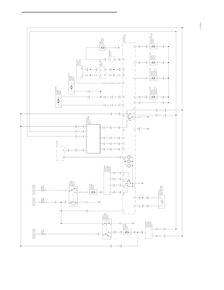
MANUAL
TEMP
CONTROL
WITH
REAR
HV
AC
HB
HVAC - ELECTRICAL DIAGNOSTICS
24 - 321
|
|
|
Content .. 1530 1531 1532 1533 ..
MANUAL TEMP CONTROL WITH REAR HV AC HB HVAC - ELECTRICAL DIAGNOSTICS 24 - 321 |