Content .. 1223 1224 1225 1226 ..
Dodge Durango (HB). Manual - part 1225
The strength of the magnetic field is the primary force
that determines the speed of operation in a particular
solenoid design. A stronger magnetic field will cause
the plunger to move at a greater speed than a weaker
one. There are basically two ways to increase the
force of the magnetic field:
1. Increase the amount of current applied to the
coil or
2. Increase the number of turns of wire in the coil.
The most common practice is to increase the number
of turns by using thin wire that can completely fill the
available space within the solenoid housing. The
strength of the spring and the length of the plunger
also contribute to the response speed possible by a
particular solenoid design.
A solenoid can also be described by the method by
which it is controlled. Some of the possibilities include
variable force, pulse-width modulated, constant ON, or
duty cycle. The variable force and pulse-width modu-
lated versions utilize similar methods to control the
current flow through the solenoid to position the sole-
noid
plunger
at
a
desired
position
somewhere
between full ON and full OFF. The constant ON and
duty cycled versions control the voltage across the
solenoid to allow either full flow or no flow through the
solenoid’s valve.
OPERATION
When an electrical current is applied to the solenoid coil, a magnetic field is created which produces an attraction
to the plunger, causing the plunger to move and work against the spring pressure and the load applied by the fluid
the valve is controlling. The plunger is normally directly attached to the valve which it is to operate. When the cur-
rent is removed from the coil, the attraction is removed and the plunger will return to its original position due to
spring pressure.
The plunger is made of a conductive material and accomplishes this movement by providing a path for the magnetic
field to flow. By keeping the air gap between the plunger and the coil to the minimum necessary to allow free move-
ment of the plunger, the magnetic field is maximized.
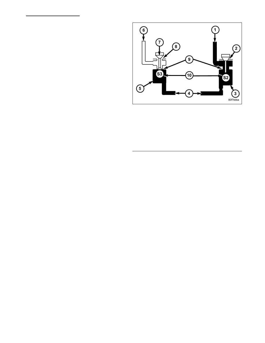
1 - OVERDRIVE CLUTCH
2 - NO VENT
3 - OVERDRIVE SOLENOID ENERGIZED
4 - MANUAL VALVE
5 - LOW REVERSE/CONVERTER CLUTCH SOLENOID DE-
ENERGIZED
6 - SOLENOID SWITCH VALVE
7 - TAPER
8 - VENT TO SUMP
9 - ORIFICE
10 - CHECK BALL
HB
AUTOMATIC TRANSMISSION 42RLE - SERVICE INFORMATION
21 - 305