Dodge Durango (HB). Manual - part 1223


  Index      Dodge     Dodge Durango (HB) - service repair manual 2005 year


Search            


Content   ..  1221  1222  1223  1224   ..


Dodge Durango (HB). Manual - part 1223


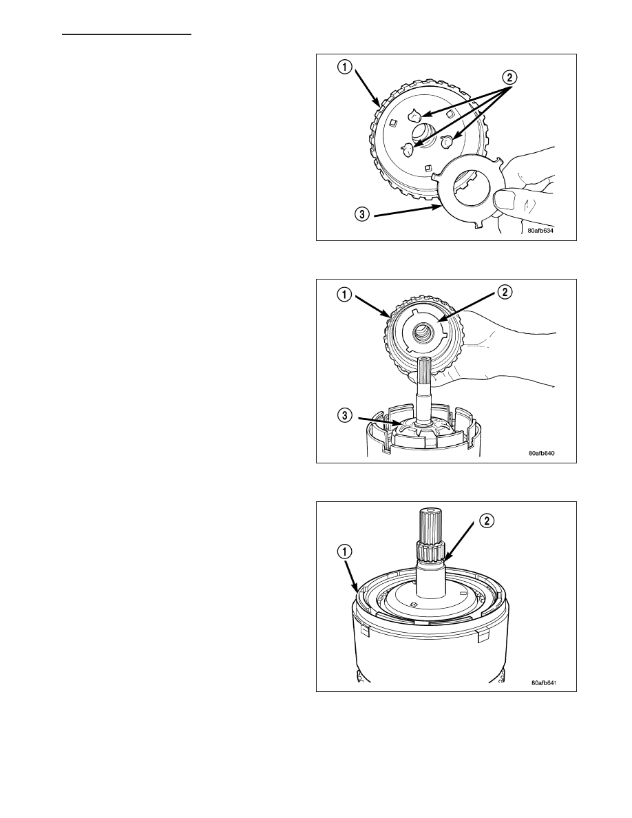
43. Install the number 3 thrust plate (3) to the bottom

of the overdrive shaft assembly (1). Retain with
petrolatum or transmission assembly gel (2).

44. Install the overdrive shaft assembly (1).

45. Reinstall overdrive and reverse clutch. Recheck-

ing these clutch clearances is not necessary.

HB

AUTOMATIC TRANSMISSION 42RLE - SERVICE INFORMATION

21 - 297

SENSOR-INPUT SPEED

DESCRIPTION

The Input (1) and Output (2) Speed Sensors are two-
wire magnetic pickup devices that generate AC signals
as rotation occurs. They are mounted in the left side
of the transmission case and are considered primary
inputs to the Transmission Control Module (TCM).

OPERATION

The Input Speed Sensor provides information on how fast the input shaft is rotating. As the teeth of the input clutch
hub pass by the sensor coil, an AC voltage is generated and sent to the TCM. The TCM interprets this information
as input shaft rpm.

The Output Speed Sensor generates an AC signal in a similar fashion, though its coil is excited by rotation of the
rear planetary carrier lugs. The TCM interprets this information as output shaft rpm.

The TCM compares the input and output speed signals to determine the following:

Transmission gear ratio

Speed ratio error detection

CVI calculation

The TCM also compares the input speed signal and the engine speed signal to determine the following:

Torque converter clutch slippage

Torque converter element speed ratio

REMOVAL

1. Raise vehicle.

2. Place a suitable fluid catch pan under the transmis-

sion.

3. Remove the wiring connector from the input speed

sensor.

NOTE: The speed sensor bolt has a sealing patch
applied from the factory. Be sure to reuse the
same bolt.

4. Remove the bolt holding the input speed sensor to

the transmission case.

5. Remove the input speed sensor from the transmis-

sion case.

21 - 298

AUTOMATIC TRANSMISSION 42RLE - SERVICE INFORMATION

HB

INSTALLATION

1. Install the input speed sensor (1) into the transmis-

sion case.

NOTE: Before installing the speed sensor bolt, it
will be necessary to replentish the sealing patch
on the bolt using Mopar

T

Lock & Seal Adhesive.

2. Install the bolt to hold the input speed sensor into

the transmission case. Tighten the bolt to 9 N·m
(80 in.lbs.).

3. Install the wiring connector onto the input speed

sensor

4. Verify the transmission fluid level. Add fluid as nec-

essary.

5. Lower vehicle.

PUMP-OIL

DESCRIPTION

The oil pump is located in the pump housing inside
the bell housing of the transmission case. The oil
pump assembly consists of an inner (3) and outer (2)
gear, a housing (1), and a cover that also serves as
the reaction shaft support (6).

OPERATION

As the torque converter rotates, the converter hub rotates the inner and outer gears. As the gears rotate, the clear-
ance between the gear teeth increases in the crescent area, and creates a suction at the inlet side of the pump.
This suction draws fluid through the pump inlet from the oil pan. As the clearance between the gear teeth in the
crescent area decreases, it forces pressurized fluid into the pump outlet and to the valve body.

HB

AUTOMATIC TRANSMISSION 42RLE - SERVICE INFORMATION

21 - 299

DISASSEMBLY

1. Remove the reaction shaft support bolts.

2. Remove the reaction shaft support(2) from the

pump housing (1).

3. Remove the pump gears (2, 3) and check for wear

and damage on pump housing (1) and gears (2, 3).

4. Re-install the gears and check clearances.

5. Measure the clearance between the outer gear (1)

and the pump pocket (2). Clearance should be
0.089-0.202 mm (0.0035-0.0079 in.).

6. Measure clearance between outer gear and cres-

cent.

Clearance

should

be

0.060-0.298

mm

(0.0023-0.0117 in.).

7. Measure clearance between inner gear and cres-

cent.

Clearance

should

be

0.093-0.385

mm

(0.0036-0.0151 in.).

8. Position an appropriate piece of Plastigage across

both pump gears.

9. Align the Plastigage to a flat area on the reaction

shaft support housing.

21 - 300

AUTOMATIC TRANSMISSION 42RLE - SERVICE INFORMATION

HB


Content   ..  1221  1222  1223  1224   ..