Dodge Durango (HB). Manual - part 1145


  Index      Dodge     Dodge Durango (HB) - service repair manual 2005 year


Search            


Content   ..  1143  1144  1145  1146   ..


Dodge Durango (HB). Manual - part 1145


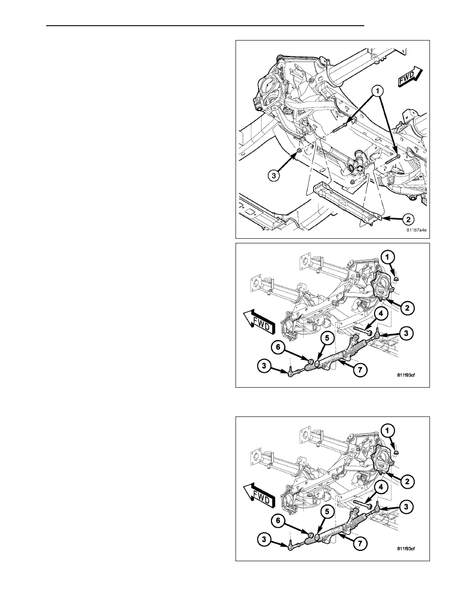
12. Remove the front crossmember (2) (Refer to 13 -

FRAME & BUMPERS/FRAME/FRONT CROSS-
MEMBER - REMOVAL).

13. Remove the steering gear mounting bolts (4),

washers (5) and nuts (6).

14. Tip the gear (7) forward to allow clearance and

move to the right then tip the gear downward on
the left side to remove from the vehicle.

INSTALLATION

NOTE: Before installing gear inspect the bushings
and replace if worn or damaged, also use new
gear mounting bolts and nuts.

1. Install gear (7) to the vehicle and tighten mounting

nuts and bolts (4&6) to 258 N·m (190 ft. lbs.).

2. Install power steering lines to steering gear and

tighten the pressure hose to 38 N·m (28 ft. lbs.)
and tighten the return hose to 65 N·m (48 ft. lbs.).
(Refer to 19 - STEERING/PUMP/HOSES - INSTAL-
LATION), (Refer to 19 - STEERING/PUMP/HOSES
- INSTALLATION).

HB

GEAR

19 - 33

3. Slide the shaft coupler (1) onto gear (3). Install

new bolt (2) and tighten to 49 N·m (36 ft. lbs.).

4. Clean tie rod end studs and knuckle tapers (5).

5. Install tie rod ends (2) into the steering knuckles (5)

and tighten the nuts (1) to 75 N·m (55 ft. lbs.).
(Refer to 19 - STEERING/LINKAGE/TIE ROD END
- INSTALLATION).

6. Install the Y-pipe (3) 3.7L & 4.7L engines only.

19 - 34

GEAR

HB

7. Install the front crossmember (2) (Refer to 13 -

FRAME & BUMPERS/FRAME/FRONT CROSS-
MEMBER - INSTALLATION).

8. Install the front tires.

9. Remove the support and lower the vehicle.

10. Unlock the steering wheel.

11. Fill system with fluid, (Refer to 19 - STEERING/

PUMP - STANDARD PROCEDURE).

12. Adjust the toe position. (Refer to 2 - SUSPEN-

SION/WHEEL

ALIGNMENT

-

STANDARD

PROCEDURE).

SPECIFICATIONS

TORQUE CHART

TORQUE SPECIFICATIONS

DESCRIPTION

N·m

Ft. Lbs.

In. Lbs.

Rack and Pinion Steering

Gear

Gear to Frame Bolts

258

190

Rack and Pinion Steering

Gear

Intermediate Shaft Bolt

38

28

Tie Rod End

Knuckle Nut

75

55

Tie Rod End

Jam Nut

130

96

Power Steering Line

Pressure Line

38

28

Power Steering Line

Return Line

65

48

HB

GEAR

19 - 35

LINKAGE

TABLE OF CONTENTS

page

page

LINKAGE

DIAGNOSIS AND TESTING

OUTER TIE ROD END

. . . . . . . . . . . . . . . . . . 36

TIE ROD END

REMOVAL - OUTER TIE ROD END

. . . . . . . . . . 36

INSTALLATION - OUTER TIE ROD END

. . . . . . 37

LINKAGE

DIAGNOSIS AND TESTING

OUTER TIE ROD END

NOTE: If the outer tie rod end is equipped with a lubrication fitting, grease the joint then road test the vehi-
cle before performing test.

1. Raise the front of the vehicle. Place safety floor stands under both lower control arms as far outboard as pos-

sible. Lower the vehicle to allow the stands to support some or all of the vehicle weight.

2. Remove the front tires.

3. Mount a dial indicator solidly to the vehicle steering knuckle and then zero the dial indicator.

4. Position indicator plunger on the topside of the outer tie rod end.

NOTE: The dial indicator plunger must be perpendicular to the machined surface of the outer tie rod end.

5. Position a pry bar in order to pry downwards on the outer tie rod end.

6. If the travel exceeds 0.5 mm (0.020 in.), replace the outer tie rod end (Refer to 19 - STEERING/LINKAGE/TIE

ROD END - REMOVAL).

7. If the outer tie rod end is within specs reinstall the front tires (Refer to 22 - TIRES/WHEELS/WHEELS - STAN-

DARD PROCEDURE).

TIE ROD END

REMOVAL - OUTER TIE ROD END

NOTE: Do not twist the boot anytime during
removal or installation.

1. Loosen the jam nut (3).

2. Remove the outer tie rod end (2) nut (1) from the

ball stud.

19 - 36

LINKAGE

HB


Content   ..  1143  1144  1145  1146   ..