Dodge Durango (HB). Manual - part 1146


  Index      Dodge     Dodge Durango (HB) - service repair manual 2005 year


Search            


Content   ..  1144  1145  1146  1147   ..


Dodge Durango (HB). Manual - part 1146


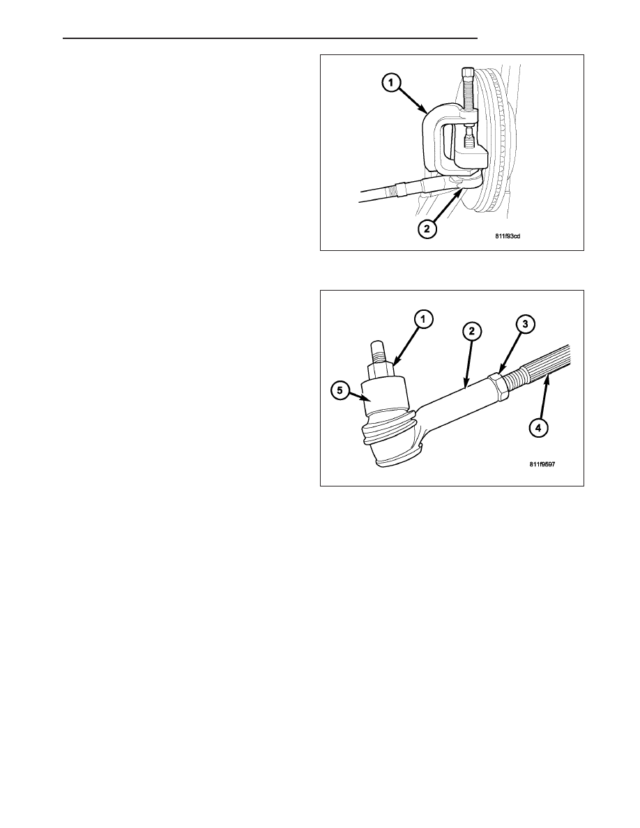
3. Separate the outer tie rod end (2) from the knuckle

with Remover 8677 (1).

4. Unthread the outer tie rod end from the inner tie

rod. Count the number of turns when removing
the tie rod end, This will give a good starting
point when reassembiling and toe adjustment.

INSTALLATION - OUTER TIE ROD END

NOTE: Do not twist the boot at anytime during
removal or installation.

1. Thread the outer tie rod end (2) onto the inner tie

rod (4), to it’s original position.

2. Install the outer tie rod end into the steering

knuckle (5).

3. Tighten the ball stud nut (1) on the ball stud to 75

N·m (55 ft. lbs.).

4. Set wheel toe pattern, (Refer to 2 - SUSPENSION/

WHEEL

ALIGNMENT

-

STANDARD

PROCE-

DURE).

5. Tighten jam nut (3) to 130 N·m (96 ft. lbs.).

HB

LINKAGE

19 - 37

PUMP

TABLE OF CONTENTS

page

page

PUMP

DESCRIPTION

. . . . . . . . . . . . . . . . . . . . . . . . . 38

OPERATION

. . . . . . . . . . . . . . . . . . . . . . . . . . . 39

DIAGNOSIS AND TESTING

PUMP LEAKAGE

. . . . . . . . . . . . . . . . . . . . . . 39

STANDARD PROCEDURE

POWER STEERING PUMP - INITIAL

OPERATION . . . . . . . . . . . . . . . . . . . . . . . . . 40

REMOVAL

. . . . . . . . . . . . . . . . . . . . . . . . . . . . . 40

INSTALLATION

. . . . . . . . . . . . . . . . . . . . . . . . . 41

SPECIFICATIONS

TORQUE CHART

. . . . . . . . . . . . . . . . . . . . . . 41

FLUID

DESCRIPTION

. . . . . . . . . . . . . . . . . . . . . . . . . 41

STANDARD PROCEDURE

POWER STEERING FLUID LEVEL

CHECKING . . . . . . . . . . . . . . . . . . . . . . . . . . 42

FLUID COOLER

REMOVAL

. . . . . . . . . . . . . . . . . . . . . . . . . . . . . 42

INSTALLATION

. . . . . . . . . . . . . . . . . . . . . . . . . 43

HOSES

REMOVAL

RETURN HOSE

. . . . . . . . . . . . . . . . . . . . . . . 44

PRESSURE HOSE

. . . . . . . . . . . . . . . . . . . . . 44

INSTALLATION

RETURN HOSE

. . . . . . . . . . . . . . . . . . . . . . . 45

PRESSURE HOSE

. . . . . . . . . . . . . . . . . . . . . 45

PULLEY

REMOVAL

. . . . . . . . . . . . . . . . . . . . . . . . . . . . . 46

INSTALLATION

. . . . . . . . . . . . . . . . . . . . . . . . . 46

RESERVOIR

REMOVAL

. . . . . . . . . . . . . . . . . . . . . . . . . . . . . 47

INSTALLATION

. . . . . . . . . . . . . . . . . . . . . . . . . 47

PUMP

DESCRIPTION

The pump (1) is connected to the steering gear (2) via
the pressure hose (3) and the return hoses (4). The
pump shaft has a pressed-on pulley (6) that is belt
driven by the crankshaft pulley.

19 - 38

PUMP

HB

The power steering oil cooler (5) is mounted to the
front lower part of the radiator (7).

NOTE: Power steering pumps are not interchange-
able with pumps installed on other vehicles.

OPERATION

Hydraulic pressure is provided for the power steering
gear by the belt driven power steering pump. The
power steering pumps are constant flow rate and dis-
placement, vane-type pumps.

DIAGNOSIS AND TESTING

PUMP LEAKAGE

The pump is serviced as an assembly and should not be disassembled. Plastic pump reservoirs can be replace and
the reservoir O-ring.

Check for leaks in the following areas:

Pump shaft seal behind the pulley

Pump to reservoir O-ring

Reservoir cap

Pressure and return lines

Flow control valve fitting

HB

PUMP

19 - 39

STANDARD PROCEDURE

POWER STEERING PUMP - INITIAL OPERATION

WARNING: THE FLUID LEVEL SHOULD BE CHECKED WITH ENGINE OFF TO PREVENT INJURY FROM MOV-
ING COMPONENTS.

CAUTION: MOPAR

T

ATF+4 is to be used in the power steering system. No other power steering or auto-

matic transmission fluid is to be used in the system. Damage may result to the power steering pump and
system if any other fluid is used, and do not overfill.

Wipe filler cap clean, then check the fluid level. The dipstick should indicate COLD when the fluid is at normal
temperature.

1. Turn steering wheel all the way to the left

2. Fill the pump fluid reservoir to the proper level and let the fluid settle for at least two (2) minutes.

3. Raise the front wheels off the ground.

4. Slowly turn the steering wheel lock-to-lock 20 times with the engine off while checking the fluid level.

NOTE: Vehicles with long return lines or oil coolers turn wheel 40 times.

5. Start the engine. With the engine idling maintain the fluid level.

6. Lower the front wheels and let the engine idle for two minutes.

7. Turn the steering wheel in both direction and verify power assist and quiet operation of the pump.

If the fluid is extremely foamy or milky looking, allow the vehicle to stand a few minutes and repeat the procedure.

CAUTION: Do not run a vehicle with foamy fluid for an extended period. This may cause pump damage.

REMOVAL

1. Drain and siphon the power steering fluid from the

pump.

2. Remove the serpentine drive belt, (Refer to 7 -

COOLING/ACCESSORY DRIVE/DRIVE BELTS -
REMOVAL).

3. Remove the reservoir return hose at the reservoir.

4. Remove the pressure hose from the pump.

5. Remove 3 pump mounting bolts through pulley

access holes.

6. Remove the pump from the engine.

19 - 40

PUMP

HB


Content   ..  1144  1145  1146  1147   ..