Dodge Durango (HB). Manual - part 1143


  Index      Dodge     Dodge Durango (HB) - service repair manual 2005 year


Search            


Content   ..  1141  1142  1143  1144   ..


Dodge Durango (HB). Manual - part 1143


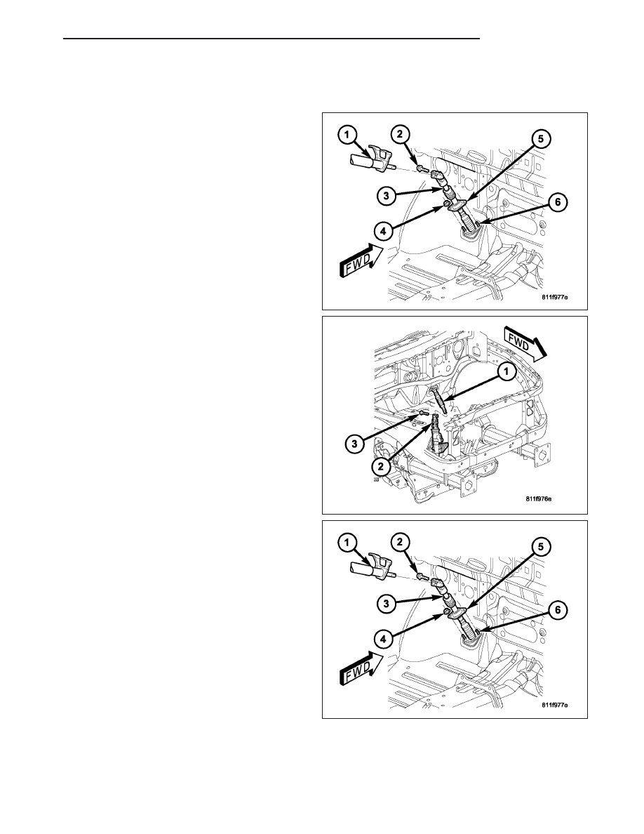
STEERING COUPLING SHAFT

REMOVAL

1. Disconnect the negative battery cable.

2. Lock the steering wheel with the tire in the straight

position.

3. Remove and discard the upper pinch bolt (2) from

the upper coupling at the cloumn (1).

4. Lower the steering coupler shaft (3) from the col-

umn (1).

5. Remove the toe plate (5) nuts (4).

6. Remove and discard the lower coupler pinch bolt

(3) from the lower steering coupling shaft (1) at the
steering gear.

7. Remove the steering coupling shaft from the

vehicle.

HB

COLUMN

19 - 25

INSTALLATION

1. Install the upper steering coupling shaft (3) to the

vehicle.

NOTE: Note: A new steering coupling shaft pinch
bolt for the upper and lower shafts must be used.

2. Install the upper coupling to the column.

3. Install the upper pinch bolt (2) use a new bolt and

tighten to 38 N.m (28 ft.lbs).

4. Install the toe plate (5) nuts (4) and tighten to 12

N.m (105 in.lbs).

5. Install the shaft (1) to the lower coupling (2).

6. Install the lower pinch bolt (3) use new bolt and

tighten to 38 N.m (28 ft.lbs).

7. Unlock the steering wheel.

8. Reconnect the negative battery cable.

LOWER STEERING COUPLING

REMOVAL

1. Disconnect the negative battery cable.

2. Raise and support the vehicle.

3. Lock the steering wheel with the tire in the straight

position.

4. Remove and discard the upper coupling (1) pinch

bolt (2).

19 - 26

COLUMN

HB

5. Remove and discard the lower coupling (2) pinch

bolt (3).

6. Remove the lower steering shaft coupling (1) from

the steering gear (3).

INSTALLATION

1. Install the coupling (1) to the steering gear (3).

HB

COLUMN

19 - 27

2. Install the other end of the coupling (2) to the

steering shaft (1).

NOTE: New pinch bolts must be used for reinstal-
lation.

3. Install the upper pinch bolt (3) and tighten to 38

N·m (28 ft. lbs.).

4. Install the lower pinch bolt (2) and tighten to 38

N·m (28 ft. lbs.).

5. Lower the vehicle.

6. Reconnect the negative battery cable.

7. Unlock the steering wheel.

TILT LEVER KNOB RELEASE

REMOVAL

1. Remove the tilt lever handle.

2. Remove the steering column opening cover (Refer

to 23 - BODY/INSTRUMENT PANEL/STEERING
COLUMN OPENING COVER - REMOVAL).

3. Remove the lower shroud.

NOTE: Use special care not to pry on the clock-
spring electrical connector when removing or
installing the mounting screw located next to the
clockspring.

4. Remove the two mounting screws (3) from the tilt

lever knob release bracket (1).

5. Disconnect the electrical harness plastic mounting

tab (2) from the the bracket (1).

19 - 28

COLUMN

HB


Content   ..  1141  1142  1143  1144   ..